Manual R06-2016 45 / 172
ROTARY INDEXING TABLE CONTROLLER
EF2...B
FUNCTION AND SIGNAL DESCRIPTIONS | 4.6 Interface assignment TM15
4.6 Interface assignment TM15
The Terminal Module provides 24 DI/DO (digital I/Os).
In the case of EF2, the digital inputs and outputs are permanently assigned as 12 DI and 12 DO.
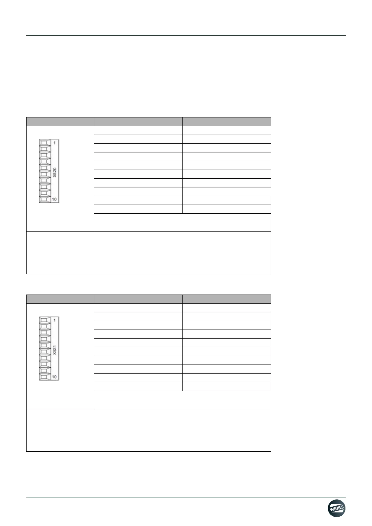
4.6.1 Interface X520
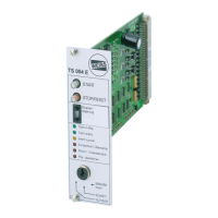
4.6.2 Interface X521
Representation Terminal Name
1 L1+
2DI 0
3DI 1
4DI 2
5DI 3
6DI 4
7DI 5
8DI 6
9DI 7
10 M1 (GND)
Screw terminal
Max. connectable cross-section: 1.5 mm
2
L1+: A 24 V DC power supply for DI/DO 0 to 7 (first potential group) must always be connected if at least one
DI/DO in the potential group is used as an output.
M1: A ground reference for DI/DO 0 to 7 (first potential group) must always be connected if at least one DI/DO
in the potential group is used as an output
.
DI/DO: Digital input / output
Representation Terminal Name
1 L2+
2DI 8
3DI 9
4DI 10
5DI 11
6DO 0
7DO 1
8DO 2
9DO 3
10 M2 (GND)
Screw terminal
Max. connectable cross-section: 1.5 mm
2
L2+: A 24 V DC power supply for DI/DO 8 to 15 (second potential group) must always be connected if at least
one DI/DO of the potential group is used as an output.
M2: A ground reference for DI/DO 8 to 15 (second potential group) must always be connected if at least one
DI/DO of the potential group is used as an output
.
DI/DO: Digital input / output