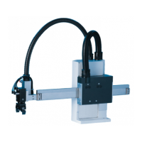
The WEISS WAS.handling Windows-Program is an operating instruction manual for a specialized handling device, likely an automated pick-and-place or positioning system, referred to as the HP140. The system is designed for precision movements and can be integrated into various automated processes.
Function Description:
The device, the HP140, is a handling system capable of precise movements along multiple axes (X, Y, Z, and A). It is controlled by a Windows-based software, WAS.handling, which allows for configuration, operation, and monitoring. The core function involves moving to and saving specific positions, executing predefined sequences of movements, and interacting with external systems via various interfaces. The system is designed to be highly configurable, allowing users to define movement parameters, create complex sequences, and integrate with supervisory PLCs or visualization programs.
Important Technical Specifications:
The HP140 system comprises a mechanical setup, a drive amplifier (ACOPOS series, e.g., ACOPOS 1016, ACOPOS 1010), and a cable set. Optionally, digital I/O modules (1 or 2 modules, each with 16 inputs and outputs) can be integrated. The control system uses a slot-CPU.
- Software Requirements: The WAS.handling software requires Windows 95 or higher, "true color" (32-bit) display settings, and Internet Explorer 5.5 or higher.
- Connectivity: Connection to the control computer (PC/laptop) is typically established via a serial RS232 cable (pin assignment: Pin 2 <-> Pin 3, Pin 3 <-> Pin 2, Pin 5 <-> Pin 5) or Ethernet (TCP/IP). A USB to RS232 adapter can be used if a serial interface is unavailable.
- Drive Amplifier: The drive amplifier receives power and control signals. It features inputs for "Enable" (emergency shut-off), "Quickstop," and a 24V power supply. Internal communication uses a CAN Bus.
- Interfaces: Customer interfaces include digital outputs, Profibus, CAN/DeviceNet, and digital inputs. Parameterization can be done via RS232 or Ethernet.
- Positioning: The system supports up to 127 storable positions.
- Sequences: Up to 32 drive sequences can be saved, each consisting of a maximum of 32 commands. A "demo sequence" feature allows for automatically restarting sequences, primarily for presentations or initial setup.
- Speed and Acceleration: Maximum speed, acceleration, and deceleration parameters are configurable for each axis. For "Jog Mode," parameters like
v_start, v_max, decel, factor, and distance are defined.
- Limits: The system monitors maximum speed, acceleration, deceleration, jerk (
t_jerk), and in-position time (t_in_pos).
- Load: The customer-specific load (gripper + work piece weight) can be entered, which automatically adjusts limit values for start and stop ramps.
- Reference Drive: The reference drive (homing) is performed against a mechanical stop. Parameters include
timeout, v1 (speed of reference drive), v2 (for reference switch methods), accel (start ramp), tr_s_block, tr_s_rel, sw_edge, trigger_dir, start_dir, ref_impulse, home order, and motor torque.
- Axis Configuration (Part 4): Includes
length (mechanical length of the axis), following error (monitoring difference between target and real position), window Profibus, encoder direction, limit switch, simulation, quick_stop_input, stop input, waittime enable, find motor phase (method, current), and motor (motor type, temp. sensor, motor torque).
- Cams: Up to 8 software cams can be parameterized, allowing for output signals based on axis position windows.
- Error Handling: The system logs the last 20 error messages with timestamps. Specific error numbers (e.g., 210 for ACOPOS Y axis error, 310 for ACOPOS Z axis error) provide detailed descriptions.
Usage Features:
- User Interface: The WAS.handling software follows standard Microsoft Windows conventions, featuring a menu bar, tool bar (with tooltips), and status bar. Inputs in text boxes are confirmed by pressing ENTER. Multiple dialog boxes can be open simultaneously.
- Parameter Management: All parameters are stored on the slot-CPU and are typically transferred immediately after input. Position data and sequences require manual transfer. Parameters can be saved to and loaded from files, even "offline" via simulation mode. When loading, specific parameter groups (HW_Config, Axis, Teached Positions, Cam, Sequence, Demo Sequence, PCM, Zero Point) can be selected for application.
- Manual Operation (Teach Positions): A dedicated dialog allows for manual movement of axes using "+" and "-" buttons. Current positions can be transferred to an input box by double-clicking or right-clicking in the "Pos" column. Maximum speed for movement to a position is configurable.
- Sequence Programming: Users can build drive sequences by selecting commands from list boxes and entering options (e.g., position numbers, wait times). Commands include "Move to Pos abs," "Move to Pos rel," "Waittime," "goto line," "goto mark," "define mark," "Link axis speed X/Y/Z," "unlink axis speed X/Y/Z," "Output A1...A8 = ON/OFF," "Wait Input1...8 = ON/OFF (msec)," "Set 'var_a'...'var_d'," "if 'var_a' >= no. jump 1 line," "if 'var_a' < no. jump 1 line," "generate alarm," "start stopwatch," "stop stopwatch," "part Counter + 1," and "End."
- Demo Sequence: A special sequence type that automatically restarts, useful for presentations or initial setup. It includes functions like "Start," "Stop," "Quick Stop," "Reference," and "Ackn."
- Hardware Configuration: Allows selection of device type, assignment of I/O signals (hardware or Profibus), and configuration of Ethernet interfaces.
- I/O Configuration: A detailed dialog for configuring digital inputs and outputs, including "Enable," "Bit A..G" (binary coded for position/sequence selection), "Search home," "Set Zero," "Jog to Pos," "Move to Pos," "Move relative," "Sequence," "Demo sequence," "Stop," "Jog X/Y/Z/A+/-," "Store Pos," "Lubr.Pump Level," "Lubr.Pump Pressure," "Parameter 2," "Alarm reset," and "Input 1..8." Outputs include "Amplifier enabled/disabled," "Reference OK," "InPos," "Ready to Start," "Error," "Error (flash)," "Battery empty," "Output_A1..A8," "Cam 1..8," "Request Lubricat.," "Paramset 2 active," "PCM active/result," and "Bit A..G."
- Manual Mode (Test Menu): Provides functions for setting up and checking axes, including current position display, reference drive, setting current position as machine zero, activation/deactivation of axes, speed override, step mode for each axis, commutation angle determination, and presetting new target positions.
- Scope (Test Menu): A diagnostic tool for recording and displaying motion parameters like speed or power, primarily for service technicians.
- Quick Start Guide: A concise guide for rapid setup, covering connection, load entry, communication configuration, manual mode, teaching positions, programming sequences, and parameterizing quick stop.
Maintenance Features:
- Lubrication: The system includes parameters for "Lubr.Pump Level" (level switch for automatic lubrication) and "Lubr.Pump Pressure" (monitoring lube function). An output signal "Request Lubricat." indicates when bearings need lubrication, potentially starting a central lubrication pump.
- Battery Monitoring: An "Battery empty" output signal indicates when batteries should be replaced.
- Error Logging: The "Alarm History" logs error messages, which are crucial for troubleshooting.
- I/O Monitor: Allows checking the current status (HIGH/LOW) of each input and output bit and forcing bits, aiding in diagnosing wiring or signal issues.
- Logbook: Stores the last 1,000 commands, useful for detecting errors in drive sequences and can be sent to WEISS service.
- Troubleshooting Guide: Provides common problems and error messages, along with potential causes and remedies, such as issues with drive errors, axes not enabling, inputs/outputs not switching, and sporadic sequence abortions. It also advises on preparing information for WEISS service, including saving parameters, log entries, and pictures of wiring.