103
Merrychef conneX
®
service and repair manual
7 Circuit boards and diagrams
Back to contents >
7 CIRCUIT BOARDS A ND DIAGRAMS
7 Circuit boards and diagrams
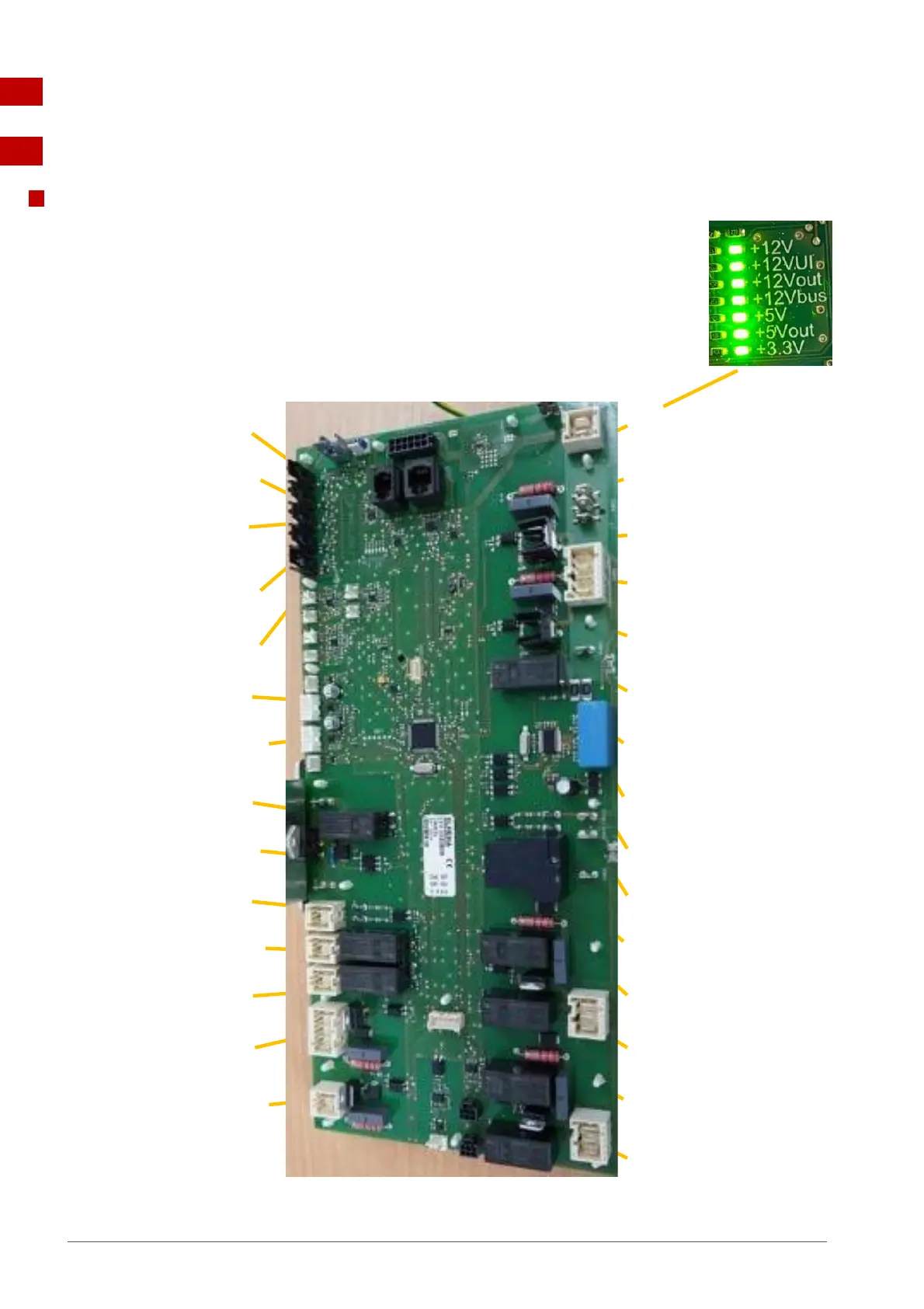
7.1 IO circuit board
IO LEDs
P-Bus – irregular flashing, indicating data communication with UI.
Run – Pulsing 1 second flash, indicating that the board has booted up.
12V, 5V & 3.3V – lit to show voltages from SMPS and inboard transformer.
Relay and triac – lit to show that a signal has been sent to energise that component.
Door switches – lit to show door closed.
Overheat thermostats – lit to show portion of closed safety circuit.
LED positions ~
LD14 – Safety circuit. Cavity heat
thermostat closed =yellow
LD9 – 12V supply from SMPS,
green = OK
LD16 – Safety circuit. RH Mag
overheat thermostat closed =
yellow
LD11 – 12V supply to UI, green =
OK
LD18 – Safety circuit. LH Mag
overheat thermostat closed =
yellow
LD10 – 12V supply to Aux circuits
green = OK
LD15 – Safety circuit. Not used,
linked out = yellow
LD12 – 12V buss supply, green =
OK
LD17 – Safety circuit. Not used,
linked out = yellow
LD30 – 5V supply from onboard
transformer, green = OK
LD19 – Run. Yellow on/off IO
board functioning
LD31 – 5V supply from onboard
transformer, green = OK
LD20 – Status. Rapid yellow
flashing, P-Bus communication
with UI
LD13 – 3.3V supply from onboard
transformer, green = OK
LD25 – Heater safety relay,
yellow = closed / OK
LD7 – Not used, yellow
LD1 – Heater drive, pulsing
yellow (varying with wattage)
LD8 – Not used, yellow
LD26 – not used, yellow LD23 – Not used, yellow
LD24 – Aux safety relay, yellow
LD6 - Door switches, yellow =
door closed
LD29 – VDF supply, yellow
LD21 – Microwave safety relay,
yellow = closed / OK
LD27 – Stirrer motor(s), yellow
LD3 – RH Magnetron, yellow = on
LD28 – Cooling Fan, on / pulsing
yellow (varying with wattage)
LD5 - MW voltage selection
relay, yellow = 200/208 VAC HV
transformer tapping
LD4 – LH magnetron, yellow = on
 Loading...