8.3.2 Assembly
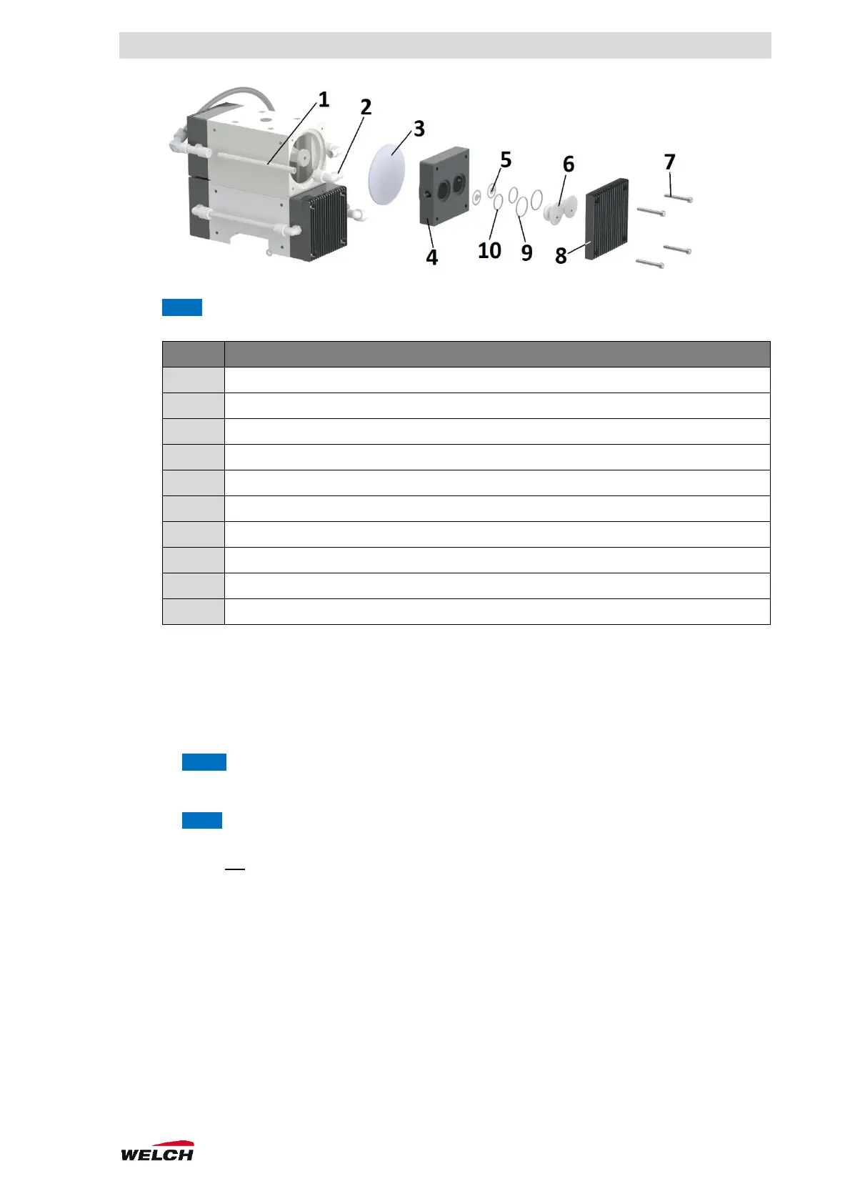
Pumping unit (Fig. 8-2)
1. Mount the diaphragm (3) tightly by hand.
2. Move the connecting rod/diaphragm (3) to the centre position.
3. Put on the pump head (4).
NOTE Position the hose connection in the compression fitting.
4. Insert the O-rings (9/10).
5. Insert valves (5):
NOTE Insert correctly, otherwise leaks will occur!
a. Ensure continuous support
b. Do not insert the burr side of the valve in the direction of the sealing surface.
6. Insert the valve inserts (6).
7. Put on the heat sink (8).
8. Tighten the cap screws (7) symmetrically.
9. Tighten the compression fitting (2).
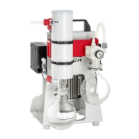
Pump in the carrier (Fig. 8-1)
1. Put the pump and carrier together.
2. Position the front side upwards.
a. Bring the spacers and screws together.
b. Fit the screws on the pump/carrier.
MXPC 303Z (2x)
MXPC 603T (4x)