ELECTRONIC
GOVERNOR
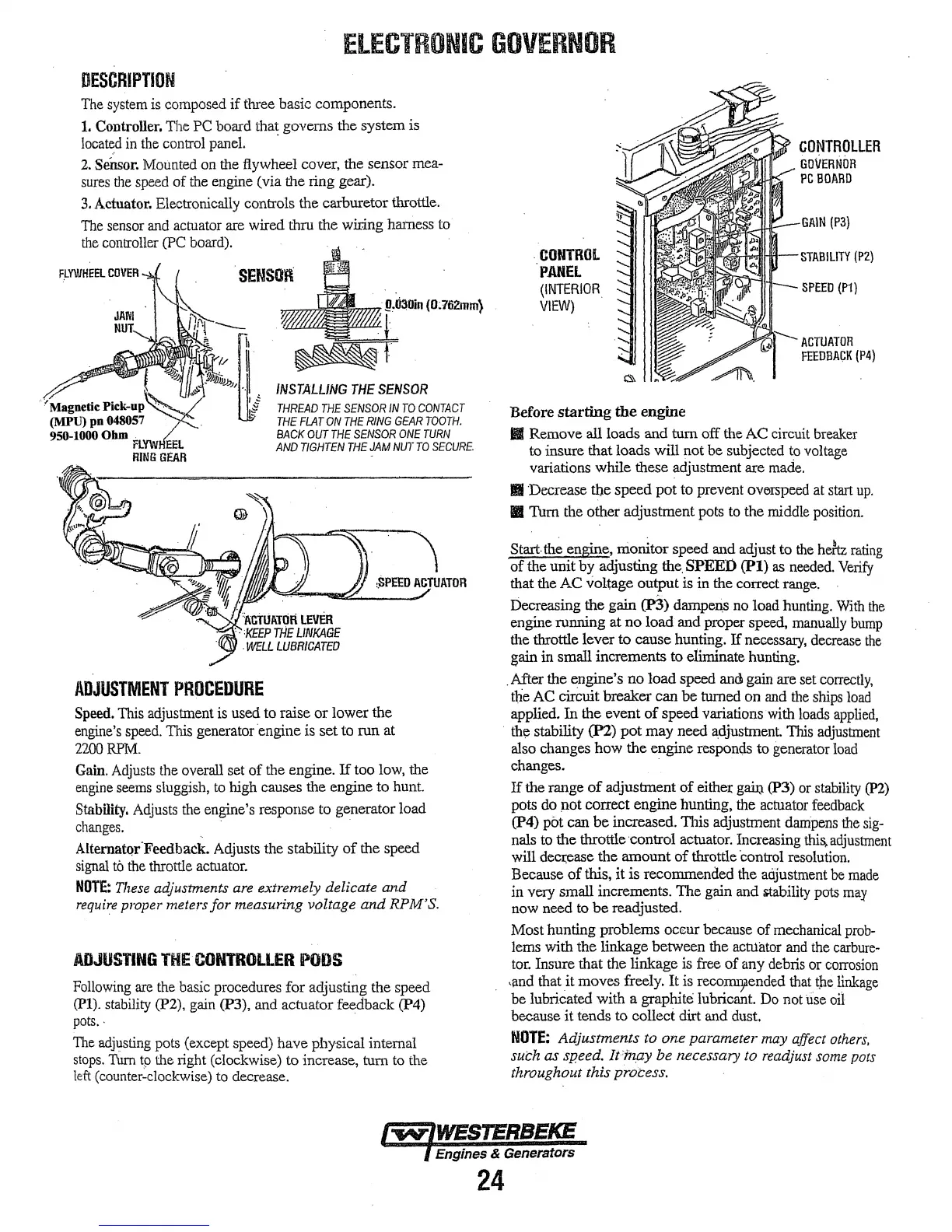
DESCRIPTION
The
system
is
composed
if
three basic components.
1.
Controller. The PC board that governs the system is
Jocate,d
in
the
control panel. ·
2.
Sensor.
Mounted on the flywheel cover, the sensor
mea-
sures
the
speed of the engine (via the ring gear).
3.
Actuator. Electronically controls the carburetor throttle.
Tue
sensor
and
actuator
are
wired thru the wiring harness
to·
the
controller
(PC
board).
.SENSOR
CONTROLLER
GOVERNOR
PG
BOARD
GAIN
(P3}
'-STABILITY
(P2}
SPEED
(P1)
;
.@~li30in
(0;762mm}
.CONTROL
PANEL
(INTERIOR
VIEW)
'/Magnetic Pick-up
(MPU) po
048057
950-1000
Ohm
FLYW
EEL
RING
GEAR
~~Wt/lb.
INSTALLING
THE
SENSOR
THREAD
THE
SENSOR
IN
TO
CONTACT
THE
Fl.AT
ON
THE
RING
GEAR
TOOTH.
BACK
OUT
THE
SENSOR
ONE
TURN
AND
TIGHTEN
THE
JAM
NUT
TO
SECURE.
,SPEED
ACTUATOR
~-
. . .
'i\-ctuATlifi
LEVER
'·
'KEEP
THE
LINKAGE
.
WELL
LUBRICATED
ADJUSTMENT
PROCEDURE
Speed.
This
adjustment is used to raise or lower the
engine's
speed.
This generator engine is set to run at
2200RPM.
Gain.
Adjusts
the overall set
of
the engine.
If
too low, the
engine
seems
sluggish, to high causes the engine to hunt.
Stability.
Adjusts
the engine's response to generator load
changes.
. ·
AlternatQr.Feedback.
Adjusts the stability
of
the speed
signal
to
the
throttle actuator.
NOTE:
Tliese adjustments are extremely delicate
and
require
proper meters
for
measuring voltage
and
RPM'
S.
ADJUSTING
THE·CONTROLLER
PODS
Following
are
the
basic procedures for adjusting the speed
(Pl).
stability
(P2),
gain
(P3), and actuator feedback (P4)
pots
..
The
adjt1sting
pots (except speed) have physical internal
stops.
Tum
tp
the right (clockwise) to increase, tum
to
the
left
(counter-clockwise)
to
decrease.
Before
starting
the
engine
ACTUATOR
FEEDBACK
(P4)
Ill
Remove all loads
and
tum
off the
AC
circuit
breaker
to insure that loads
will
not be subjected
to
voltage
variations while these adjustment are
made.
Ill Decrease the speed
pot
to
prevent
overspeed
at start
up.
IB
Tum the other adjustment pots to the middle
position.
Start.
th~
engix,>.e,
monitor speed
and
adjust to
the
hek
rating
of
the unit by adjusting
the.
SPEEO
(Pl)
as
needed.
Verify
that the
AC
voltage output is in the correct range.
Decreasing the gain
(P3)
damp~
no
load hunting.
With
the
engine running at
no
load and proper speed,
manually
bump
the throttle lever to cause hunting.
If
necessary,
decrease
the
gain in small increments to eliminate hunting .
. After the engine's no load
speed
and gain are set
correctly,
the
AC
circuit breaker can
be
turned on
and
the
ships
load
applied.
In
the
event
of
speed variations with
loads
applied,
· the stability
(P2)
pot
may
need
a,djustment.
This
adjustment
also changes how the engine
respom;ls
to generator
load
24
changes. · ·
If
the range
of
adjustment
of
eithe:t:
ga:i:Q
(P3)
or
stability
(P2)
pots do ,iot correct engine hunting, the actuator
feedback
(P4)
pot can
be
increased. This adjustment
dampens
the
sig-
nals to the throttle ·control actuator. Increasing
this.
adjustment
will deci:ease the amount
of
throttle 'control
resolution.
Because
of
this, it is recommended the aojustment
be
made
in very small increments. The gain and itability pots
may
now
need
to
be
readjusted.
Most hunting problems
oceur because
of
mechanical
prob-
lems with the linkage between the
actl.lator
and
the
carbure-
tor.
Insure that the linkage
is
free
of
any debris or
corrosion
·and that it moves freely.
It
is
recoIIllJilended
that
!:}le
linkage
be lubricated with a graphite lubricant.
Do
not
use
oil
because
it
tends to collect dirt and dust.
NOTE:
Adjustments to
one
parameter may affect
others,
such
as
speed. /i"inp.y be necessary to readjust some pots
throughout this
process.