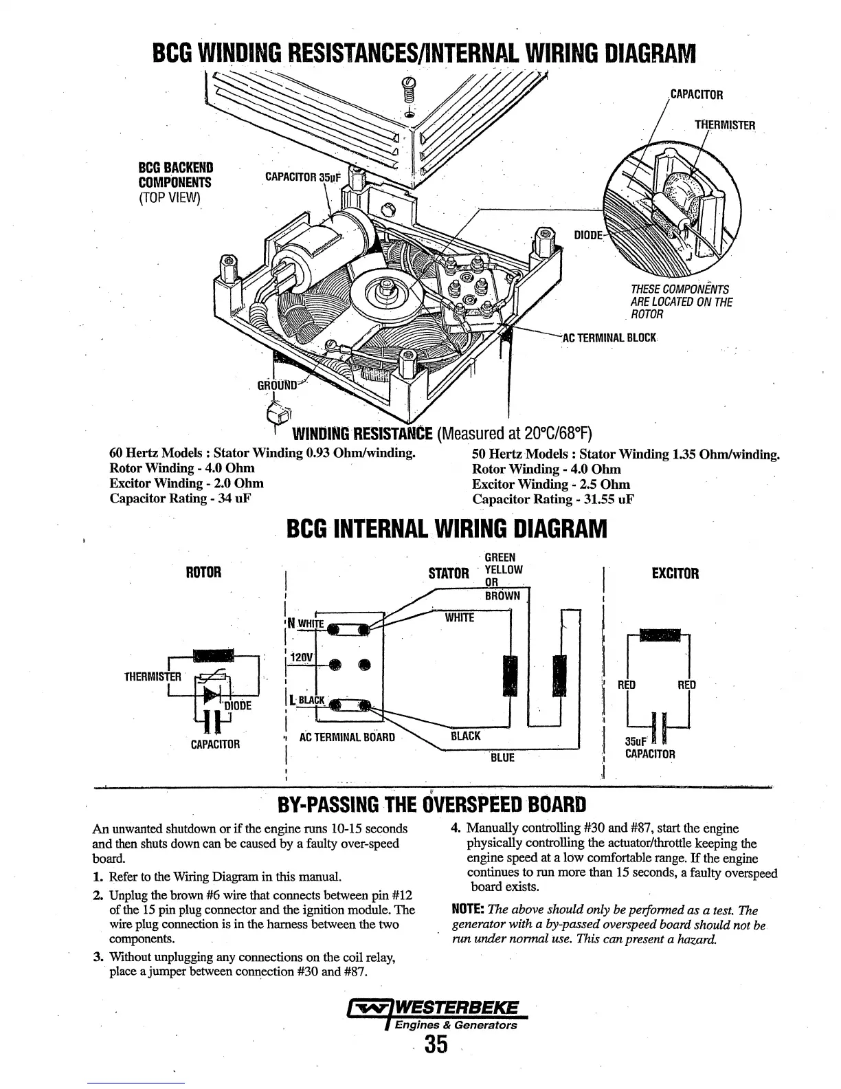
BCGBACKEND
COMPONENTS
(TOP
VIEW)
.
GROOND~
· .
.CAPACITOR
IBESE
COMPONENTS
ARE
LOCATED
ON
THE
.
ROTOR
.
.
AC
TERMINAL
BLOCK
-$;i
WllllJINtl
RESISTAflCE
(Measured
at
200C/68'F)
. .
60
Hertz Models :
Stator
Winding 0.93 Ohm/winding. 50 Hertz Models : Stator Winding 1.35 Ohm/winding.
Rotor Winding
-
4~0
Ohm
Rotor Winding - 4.0
Ohm
Excitor Winding - 2.0
Qhm
Excitor Winding
..
2.5
Ohm
Capacitor Rating - 34
uF
Capacitor Rating - 31.55
uF
BCG
INTERNAL.WIRING
DIAGRAM
·GREEN
ROTOR
STATOR
·YELLOW
EXCITOR
OR
I
BROWN
I
•N.WHITE
WHITE
I - .
ri
'12ov·
1·
-.
•
THERMISTER
.
I
!i
RED
RED
luiA
K.
61~
' .
I
:1
,
BLACK
:I
I
BLUE
:I
CAPACITOR
;1
,I!
' .
''
·.
.
BY-PASSING
THE
OVERSPEED
BOARD
An
unwanted
shutdown
or
if
the
engine
runs
10-15 seconds
and
then
shuts
down
can
be caused
by
a faulty over-speed
board.
1.
Refer
to
the
Wtting
Diagram in this manual.
2.
Unplug
the
brown
#6 wire that connects between pin #12
of
the
15
pin
plug
connector and the ignition module. The
wire
plug
connection
is in
the
harness between the
two
components.
3.
Without
unplugging
any
connections on the coil
relay,
·
place
a jumper
between
connection #30 and #87.
4.
Manually controlling #30 and
#87,
start
the
engine
physically controlling the actuator/throttle keeping
the
engine speed at a low comfortable
range.
H
the
engine
continues to
run
more than 15
seconds,
a faulty
overspeed
board exists.
NOTE:
The above should only be perfonned as a
test.
The
generator with a by-passed overspeed board should not
be
run under nonnal
use.
This can present a hazard.
Engines
&
Generators
-
35'
 Loading...