ENGINE
ADJUSTMENTS
NOTE:
WESTERBEKE
recommends
that
the
following engine adjust-
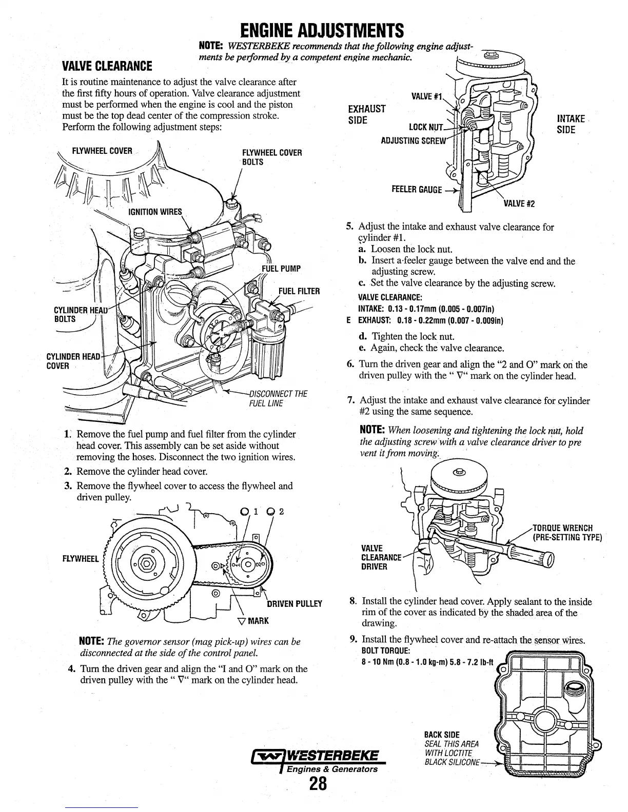
VALVE
CLEARANCE
ments be performed
~-a
competent engine mechanic.
It
is routine
mainterni.nce
to
adjust
the
valve clearance after
the
first
fifty hours of operation.
Valve
clearance adjustment
must
be
performed
when
the
engine is
cool
and
the
piston
must
be the
top
dead
center of
the
compression
stroke.
Perform the following adjustment
steps:
FLYWHEEL
COVER
BOLTS
1.'
Remove
the
fuel
pump
and
fuel
filter
from
the
cylinder
head
cover.
This
assembly
can be set
aside
without
removing
the
hoses.
Disconnect
the
two
ignition
wires.
2. Remove the cylinder
head
cover.
FLYWHEEL
NOTE:
The
governor sensor (mag pick-up)
wires
can
be
disconnected at
the
side
of
the
control
panel.
4.
Tum
the driven gear
and
align the "I
and
O"
mark on the
driven pulley
with
the
"
V"
mark on
the
cylinder
head.
EXHAUST
SIDE
FEELER
GAUGE
5.
Adjust
the
intake
and
exhaust valve clearance
for
rYlitider
#
i.
a. Loosen
the
lock
nut.
INTAKE.
SIDE
b. Insert a·feeler gauge between
the
valve
end
and
the
adjusting
screw.
c.
Set
the
valve
clearance by the adjusting
screw.
~ALVE
CLEARANCE:
INTAKE:
0.13
-
0.17mm
(0.005
•
0.007in)
E
EXHAUST:
0.18
-
0.22mm
(0.007
-
0.0091n)
d. Tighten
the
lock
nut.
e.
Again,
check
the
valve clearance.
6.
Tum
the driven gear
and
align the "2
and
O"
mark
ori
the
driven pulley with
the
" V" mark on
the
cylinder
head.
7.
Adjust
the
intake
and
exhaust valve clearance fot cylinder
#2
using
the
same
sequence.
NOTE:
When
loosening and tightening
the
lock
ri.'ut,
hold
the
adjusting
screw
·with
a valve clearance driver
to
pre
vent it from
moving:_
'
VALVE
CLEARANCE
DRIVER
8.
Install
the
cylinder head
cover'.
Apply
sealant to
the
inside
rim
of
the
cover
as
indicated
by
the
shaded
area
of
the
drawing.
· · · · · ·
9. Install
the
flywheel
cover
and
re-attach
the
sensor
Wires
BOLTTORQUE:
. . . .
..
. . •
8 -
10
Nm
(0.8
-1.0
kg-m)
5.8
- 7
.2
lb-ft
BACKSIDE
SEAL
THIS
AREA
WITH
LOCTltE
OJJl=ii===l~::;;::!!;::ttlc
Engines & Generators
BLACK
SIL/CONE':""..~-&+-41---11-1.))
28