CONTROL
PANELS
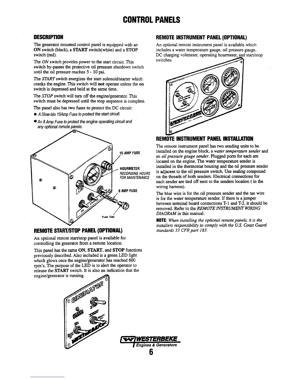
DESCRIPTION
The generator
mounted
control panelis equipped
with
an
ON switch
(black),
a
START
switch(white) and a STOP
switch (red).
The ON switch provides power to the start circuit.
nus
switch by-passes
the
pr;otective
oil pressure shutdown switch
until the oil pressure reaches
S -
10
psi.
The
START
switch
energizes the start solenoid/starter which
cranks the engine.
1bis switch will not operate unless
the
on
switch is
depressed
and
held at
the
same time.
The STOP switch
will
tum off the engine/generator.
nus
switch must
be
depressed until the stop sequence is complete.
The panel also
has
two
fuses
!O
protect the DC circuit:
•·A
Slow-blo
15Amp
Fuse
to
protect
f;tle
start:
c;ireuit.
•An
8
Amp
Fuse
to
protect
the
engine
operating
circuit
and
any
optitmal
ref!iote.
_paf!elS.
15AMPFUSE
HOURMETER
RECORDING
HOURS
FOR
MAINTENANCE
8AMPFUSE
REMOTE
START/STOP
PANEL
(OPTIONAL)
An optional
remote
start/stop panel
is
available
for
controlling
the
generator
frOm
a remote location.
This panel
has
the
same ON, START,
and
STOP functions
previously described. Also included
is
a green
LED
light
which glows
once
the
engine/generator has reached 600
rpm' s. The purpose
of
the
LED is to alert
the
operator
to
release the START switch. It
is
also an indication that
the
engine/generator is running.
()
/
o~
~
,~~
~
REMOTE
INSTRUMENT
PANEL
(OPTIONAL)
An
optional remote instrument
panel
is
available
which
includes a water temperature gauge,
oil
pressure gauge, ·
DC charging voltmeter, operating
hounneter.!.
IU!.d
start/stop
switches.
REMOTE
INSTRUMENT
PANEL
INSTAllATION
The remote instrument panel has
two
sending units to be
installed
on
the engine block, a water
temperature
sender and
an
oil
pressure
gauge
sender. Plugged ports
for
each
are
locate<i
on
the
engine.
The
water temperature sender is
installed in the thermostat housing
and
the
oil
pressure sender
is
adjacent to
the
oil
pressure
switch. Use sealing compound
on
the
threads
of
both senders. Electrical connections for
each sender are tied off next
to
the senders location ( in the
wiring harness).
The blue wire is for the oil pressure sender
and
the tan wire
is
for
the water temperature sender.
If
there
is
a jumper
between
terminal board connections
T-1
and
T-2,
it should
be
removed.
Refer
to
the REMOTE
INSTRUMENT
WIRING
DIAGRAM
in this manual.
NOTE:
When
installing the optional
remote
panels,
it is
the
installers responsibility
to
comply
with
the
U.S.
Coast
Guard
standards
33
CFR
part
183.
Engines & Generators
6 .