ENGINE
ADJUSTMENTS
NOTE:
WESTERBEKE
recommends
that the following engine
adjustments
be
performed
by
a competent engine
mechanic.
The
z"nfoniiation
below
is provided
to
assist the
mechanic,.
VALVE
CLEARANCE
ADJUSTMENT
NOTE:
Retorque the cylinder head bolts before adjusting
the
engine's
valves
(see
TORQUING
THE CYUNDER
HEAD
BOLTS).
1.
Remove the rocker cover and gasket
2.
Rotate the crankshaft in the normal direction
of
rotation,
placing
the
No.
1 piston at the top of its compression
stroke with the exhaust and intake valves completely
closed. Adjust the intake
and
exhaust valves for
No.
1
cylinder,
the exhaust valve
for
No. 2 cylinder,
and
the
intake valve
for
No.
3 cylinder (see chart).
3. Rotate the crankshaft
180"
in its
normal
direction
of
rotation. Locate
the
piston
in
No. 1 cylinder at the
top
of
its exhaust stroke. Adjust the intake valve for
No.
2
cylinder and the exhaust valve for
No.
3 cylinder (see
chart).
CYLINDER#
CRANK
ANGLE
1 2 3
When
No.
1
piston
is
set
at
top
of
IN
• •
compression
stfOke
•
•
EX
When
No.
1
piston
is
positioned
IN
•
at
top
of
exhaust
stroke
EX
•
4
••
Replace the rocker cover along with a new rocker cover
gasket..
ROCKER
COVER
TORQUE:
2.9
•
5.1
lb-ft
(0.4
•
0.7
kg·m)
VALVE
CLEARANCE
HOT:
IN
0.25mm
(0.0098
In)
EX
0.30mm
(0.0118
in)
IGNmON
TIMING
1.
Attach
a timing light
to
the
#1
spark
plug
and
mark
the
front timing pointer to indicate
10".
Locate the timing
mark
on
the crankshaft
pulley
and
mark
it
with
white
chalk or crayon.
2. Start the engllie and
warm
it
up
to
its
nonnal operating
temperature.
Make sure
the
generator is operating
without
a load on
it.
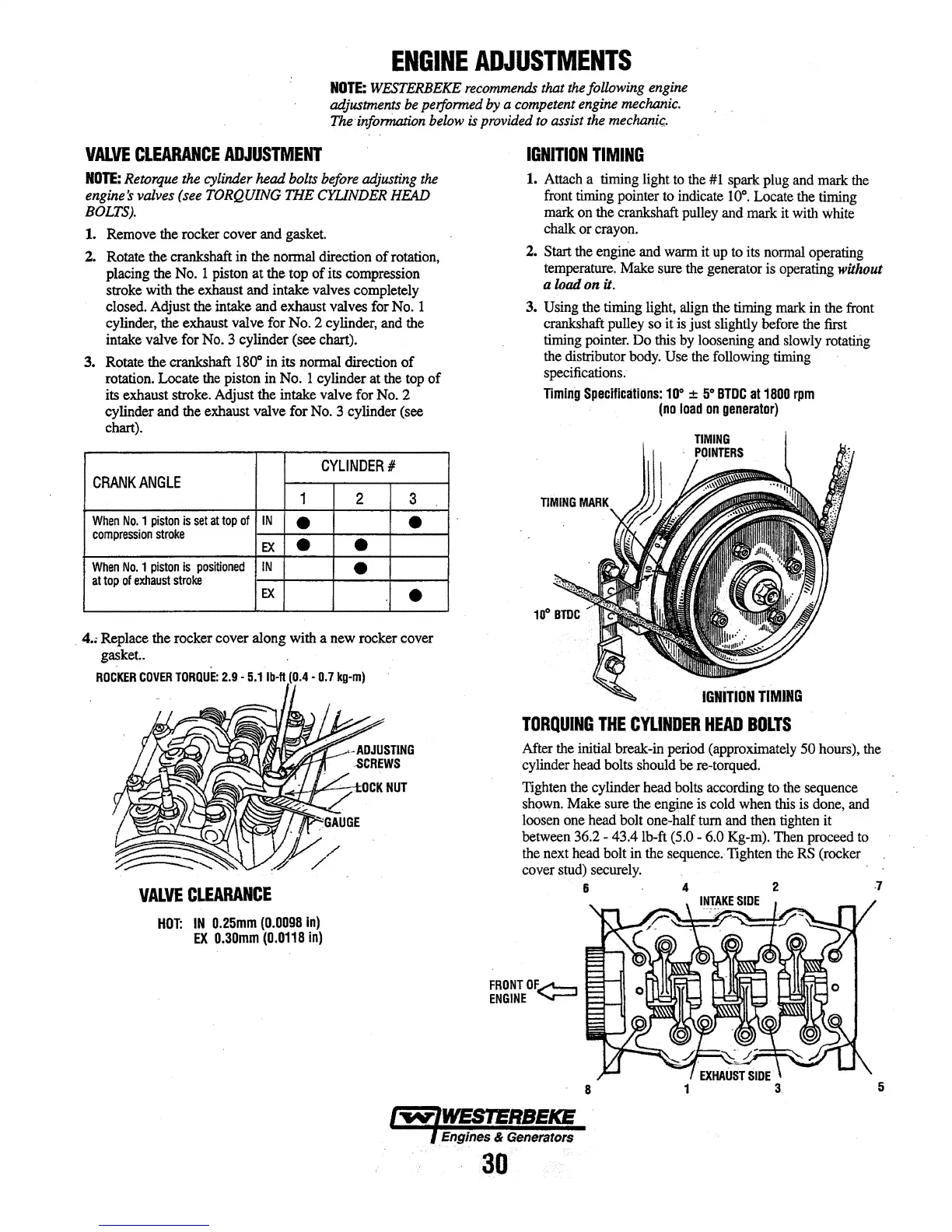
3.
Using
the timing light,
align
the
timing
mark
in
the
front
crankshaft pulley so it
is
just slightly before
the
first
timing
pointer.
Do
this
by
loosening and
slowly
rotatiiig
the
distributor
body.
Use
the
following
timing
specifications.
Timing
SpecHicallons:
111°
:1:
5°
BTDC
at
1800
rpm
(no
load
on
generator)
IGNITION
TIMING
TORQUING
THE
CYLINDER
HEAD
BOLTS
After
the
initial break-in
period
(approximately 50 hours),
the
cylinder head bolts should
be
re-torqued.
Tighten
the cylinder head bolts according to
the
sequence
shown.
Make sure the engine is cold when
this
is
done,
and
loosen
one
head bolt one-half tum
and
then
tighten
it
between 36.2 - 43.4 lb-ft
{5.0
-
6.0
Kg-m).
Then
proceed
to
the
next
head bolt in the
sequence.
Tighten the
RS
(rocker
cover
stud)
securely.
6 4 2
,7
FRONT
OF..,....,__,
ENGINE
......,._....
5
30