ENGINE
ADJUSTMENTS
NOTE:
WESTERBEKE
recommends
that
the
following
engine
adjustments
be
peiformed by a competent
engine
mechanic.
The
information
below
is provided
to
assist
the
mechanic.
ENGINE
SPEED
(HERTZ)
ADJUSTMENT
Governor
The
belt-driven, mechanically operated governor maintains
the engine's rpm under various load conditions. Engine speed
determines the hertz and voltage output
of
the generator.
Governor
Adjustments
Operate the generator to bring the unit up to operating
temperature before adjusting the governor.
NOTE:
If
the
governor
is
severely out
of
adjustment, manually
adjust
the
linkage
at no-load
to
obtain a
safe
output
voltage
before proceeding
with
the
adjustment.
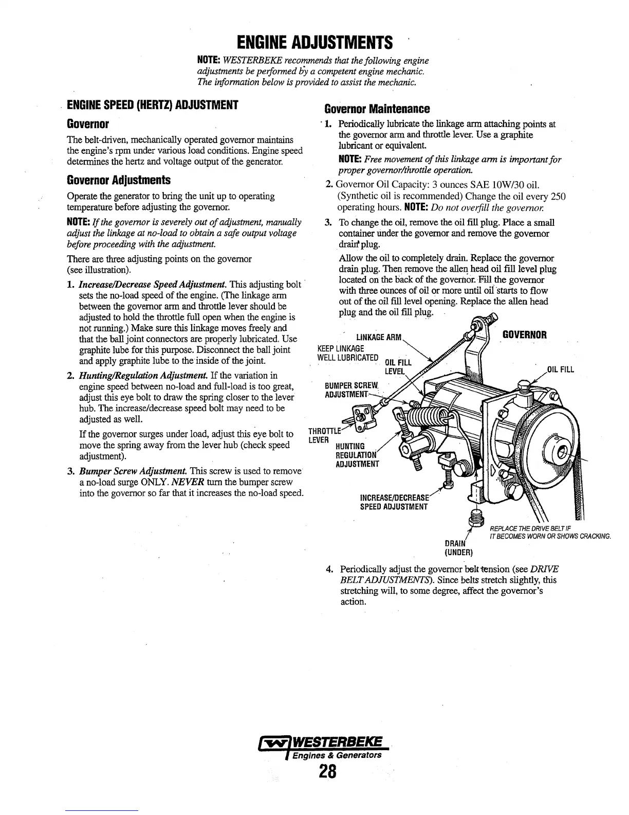
There are three adjusting points on the governor
(see illustration).
1.
Increase/Decrease
Speed Adjustment. This adjusting bolt ·
sets the no-load speed
of
the engine. (The linkage arm
between the governor arm and throttle lever should be
adjusted to hold the throttle full open when the engine is
not running.) Make sure this linkage moves freely and
that the ball joint connectors are properly lubricated.
Use
graphite lube for this purpose. Disconnect the ball joint
and apply graphite lube to the inside
of
the joint.
2.
Hunting/Regulation Adjustment.
If
the variation in
engine speed between no-load and full-load is too great,
adjust this eye bolt to draw the spring closer to the lever
hub. The increase/decrease speed bolt may need to be
adjusted as well.
If
the governor surges under load, adjust this eye bolt to
move the spring away from the lever hub (check speed
adjustment).
3.
Bumper
Screw
Adjustment. This screw is used to remove
a no-load surge
ONLY.
NEVER
tum the bumper screw
into the governor so far that
it
increases the no-load speed.
Governor
Maintenance
· 1. Periodically lubricate the linkage
arm
attaching points at
the governor arm and throttle lever.
Use a graphite
lubricant
or
equivalent
NOTE:
Free
movement
of
this
linkage arm is imponant for
proper governor/throttle operation.
2.
Governor
Oil Capacity: 3 ounces
SAE
lOW/30 oil.
(Synthetic oil is recommended)
Change
the oil every 250
operating hours.
NOTE:
Do
not
oveifill the governor.
3. To change the oil, remove the oil
fill
plug. Place a small
container under the governor and remove
the
governor
drallt plug.
Allow the oil to completely drain. Replace
the
governor
drain plug. Then remove the
alle~
head oil fill level plug
located on the back
of
the governor. Fill the governor
with three ounces
of
oil
or
more until oil ·starts
to
flow
out
of
the
oil
fill
level opening. Replace
the
allen head
plug and the oil
fill
plug.
LINKAGE
ARM
KEEP
LINKAGE
WELL
LUBRICATED
THRO
TILE
LEVER
HUNTING
.
REGULATION
ADJUSTMENT
INCREASE/DECREASE
SPEED
ADJUSTMENT
4. Periodically adjust the governor belt tension (see DRIVE
BELT ADJUSTMENTS). Since belts stretch slightly, this
stretching will, to some degree, affect the governor's
action.
Engines & Generators
28