COOLING
SYSTEM
DESCRIPTION
Westerbeke marine engines
are
designed and equipped for
fresh water cooling. Heat produced in the engine by combus-
tion and friction is transferred to fresh water coolant which
circulates throughout the engine. This circulating fresh water
coolant cools
the
engine block, its internal moving parts, and
the engine oil.
The
heat is transferred externally from the
fresh water coolant to raw
water
by means
of
a heat
exchanger, similar in function to an automotive radiator. Raw
water flows through the tubes
of
the heat exchanger while
fresh water coolant flows around
th~
tubes; engine heat trans-
ferred to
the
fresh water coolant is conducted through the
tube walls
to
the
raw water
which
is then pumped into the
exhaust system where finally
it
is
discharged overboard.
In other words, the engine is cooled by fresh water coolant,
this coolant is cooled
by
raw water, and the raw water carries
the transferred heat overboard through the exhaust system.
The
fresh water coolant
and
raw
water circuits are indepen-
dent
of
each
other. Using only fresh water coolant within the
engine allows the cooling water passages to stay clean and
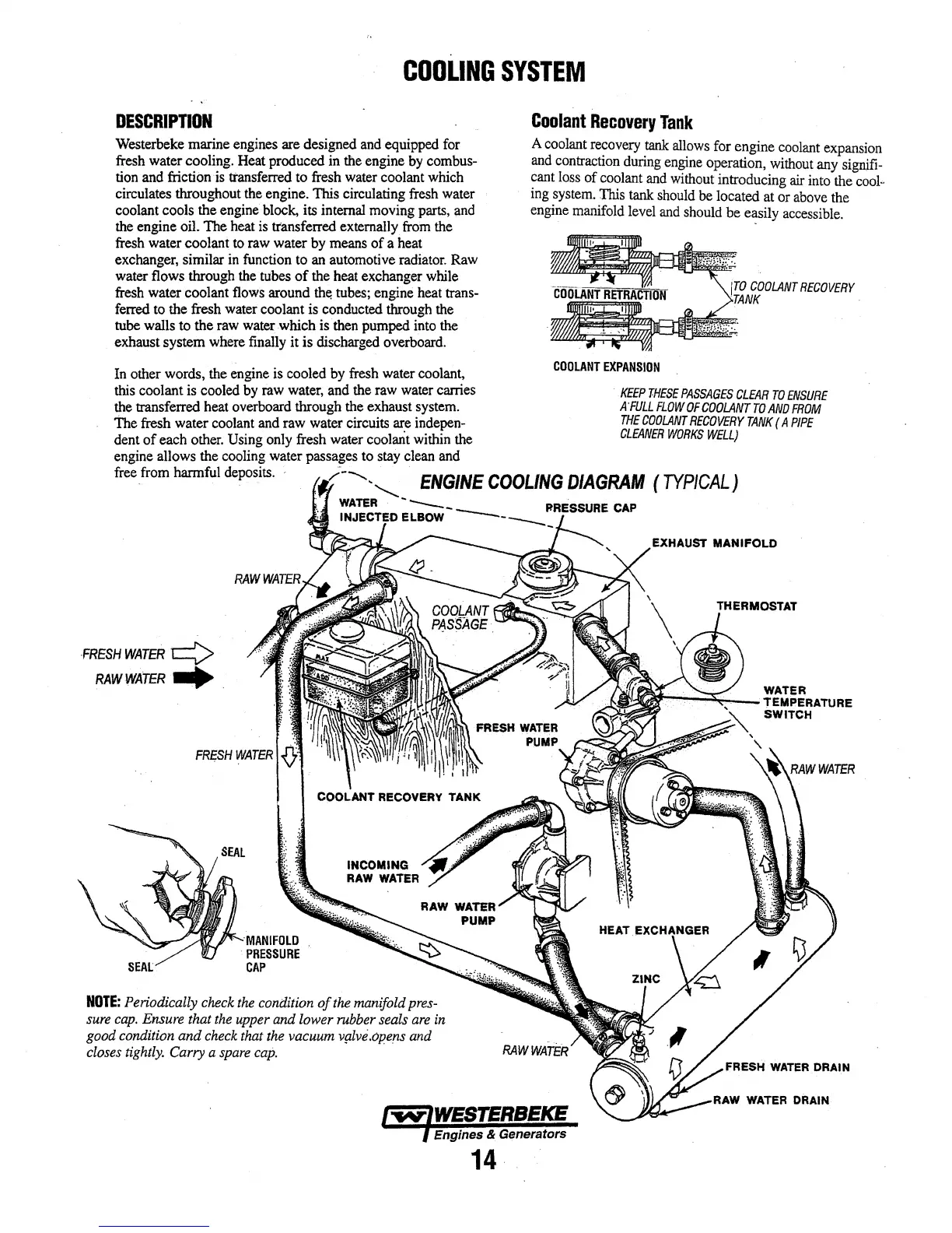
Coolant
Recovery
Tank
A coolant recovery
tank
allows for engine coolant expansion
and contraction during engine operation, without any signifi-
cant loss
of
coolant and without introducing
air
into the cool··
ing system. This tank should
be
located at or above the
engine manifold level and should
be
easily accessible.
jTO
COOLANT
RECOVERY
TANK
·
COOLANT
EXPANSION
KEEP
THESE
PASSAGES
CLEAR
TO
ENSURE
A
'FULL
FLOW
OF
COOLANT
TO
AND
FROM
THE
COOLANT
RECOVERY
TANK
(A
PIPE
CLEANER
WORKS
WELL)
free from harmful deposits. ,,..·--.._'-......_
ENGINE
COOLING
DIAGRAM
(TYPICAL)
WATER
---..
-
--
FIRESSURE
CAP
INJECTED ELBOW
----
FRESH
WATER¢
RAWWATER
....
MANIFOLD
·PRESSURE
CAP
INCOMING
RAW
WATER
NOTE:
Periodically check
the
condition
of
the
manifold pres-
sure
cap.
Ensure that
the
upper and lower rubber seals
are
in
good condition
and
check that the vacuum vplve.opens and
closes tightly. Carry a
spare
cap.
14
RAW
WATER
DRAIN