CAMSHAFT
AND
RO-CKER
ARMS
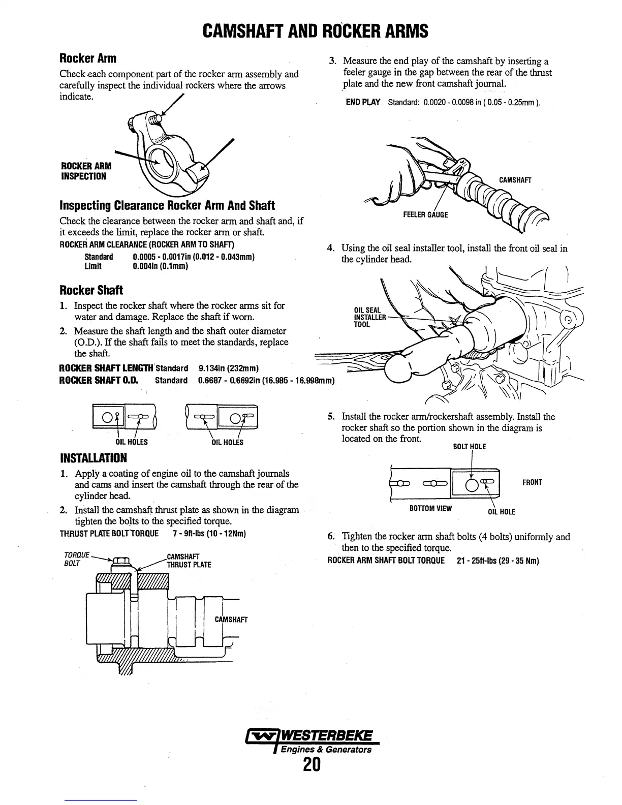
Rocker
Arm
Check each component part
of
the rocker arm assembly and
carefully inspect the individual rockers where the arrows
indicate.
ROCKER
ARM
INSPECTION
Inspecting
Clearance
Rocker
Arm
And
Shaft
Check the clearance between the rocker arm and shaft and,
if
it exceeds the limit, replace the rocker arm or shaft.
ROCKER
ARM
CLEARANCE
(ROCKER
ARM
TO
SHAFT)
Standard
0.0005
•
0.0017in
(0.012
•
0.043mm)
Limll
0.004in
(0.1mm)
Rocker
Shaft
1. Inspect the rocker shaft where the rocker arms sit for
water and damage. Replace the shaft
if
worn.
2. Measure the shaft length and the shaft outer diameter
(O.D.).
If
the shaft fails to meet the standards, replace
the shaft.
ROCKER
SHAFT
LENGTH'standard
9.1341n
(232mm)
3. Measure the
end
play
of
the camshaft by inserting a
feeler gauge in the gap between the rear
of
the thrust
_plate
and the new front camshaft journal.
END
PLAY
Standard:
0.0020-
0.0098
in
(
0.05-
0.25mm
).
4. Using the oil seal installer tool, install the front oil seal in
the cylinder head.
ROCKER
SHAFT
0.0. Standard 0.6687-
0.66921n
(16.985 -16.998mm)
~
~~II
or]
I
OIL
HOLES
OIL
HOLES
INSTALLATION
1. Apply a coating
of
engine oil to the camshaft journals
and cams and insert
the
camshaft through the rear
of
the
cylinder head.
2. Install the camshaft
thrust plate as shown in the diagram .
tighten the bo}ts to the specified torque.
THRUST
PLATE
BOLTTORQUE
7-
91t-lbs
(10
-12Nm)
TORQUE
BOLT
5. Install the rocker arm/rockershaft assembly. Install the
rocker shaft so the portion shown in the diagram
is
located on the front.
BOLT
HOLE
FRONT
BOTTOM
VIEW
.
OIL
HOLE
6.
Tighten the rocker arm shaft bolts (4 bolts) uniformly and
then to the specified torque.
ROCKER
ARM
SHAFT
BOLT
TORQUE
21
•
25ft·lbs
(29
•
35
Nm)
Engines & Generators
20
 Loading...