en-US Installation and electrical connection
16 WILO SE 2017-03
WARNING
Separation of the pressure hose!
Separation or movement of the pressure hose can
result in (serious) injuries. Attach pressure hose se-
curely to the outlet! Prevent buckling of the pres-
sure hose.
NOTICE
Delivery problems due to low water level
The hydraulics are self-venting. As a result, small air
cushions are dissolved during the pump process. If
the fluid is lowered too low, it can stop the volume
flow. The minimum permissible water level must
reach up to the upper edge of the hydraulics hous-
ing!
For portable installation the pump is equipped with a
pump support foot. The pump support foot ensures the
minimum ground clearance in the suction area and al-
lows secure footing on a firm foundation. Thus in this
installation type, any positioning in the operating
space/installation site is possible. To prevent sinking on
soft bearing surfaces, a hard base must be used at the
installation site. A pressure hose is connected on the
pressure side.
CAUTION!If the motor emerges during operation,
adhere to the operating mode for non-immersed op-
eration (S2-15, S3 10%*)!
* If the required cooling of the motor is ensured before
a re-activation, the operating mode S3 25% is permis-
sible! To ensure the required cooling, the motor must
be completely immersed for at least 1minute!
Work steps
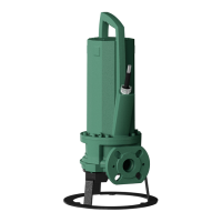
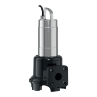
Fig.7: Wet well installation, portable
1 Pump with integrated pump support foot
2 Pipe elbow with hose connection or Storz pipe coupling
3 Storz hose coupling
4 Pressure hose
5 Attachment point
6 Lifting equipment
CAUTION
Damage to the pump due to improper instal-
lation
Observe the following points during pump installa-
tion:
• Adhere to the maximum permissible tightening
torque: 15Nm (V05) or 25Nm (V06)
• Do not insert an additional gasket between the
flange and the accessories! A gasket is mounted
on the pump flange!
• Only use accessories with a flange shape in ac-
cordance with EN1092-2, type A. The use of
other flange shapes is not permissible!
‡ Pressure connection prepared: Pipe elbow mounted
with hose connection or pipe elbow with Storz cou-
pling.
1. Attach lifting equipment to the attachment point of
the pump with a shackle.
2. Raise pump and set down on the intended work place
(pump chamber, pit).
3. Place pump on a firm foundation. CAUTION!Sinking
must be prevented!
4. Lay the pressure hose and fasten it to a certain point
(e.g. drainage). DANGER!Separation or movement of
the pressure hose can lead to (serious) injury! Attach
pressure hose securely to the outlet.
5. Correctly route power supply cable. CAUTION!Do not
damage power supply cable!
▶ Pump is installed, the qualified electrician can carry out
the electrical connection.
6.4.6 Level control
Using a level control device the current fluid levels can
be determined and the pump automatically switched
on and off depending on the fluid level. The recording
of the fluid level is made here by various sensor types
(float switches, pressure and ultrasound measurements
or electrodes). When using a level control device ob-
serve the following points:
▪Float switches can move freely!
 Loading...