en-US Installation and electrical connection
18 WILO SE 2017-03
6.5.2.2 Checking resistor in the temperature sensor
Check resistor in the temperature sensor with an ohm-
meter. The bimetallic strip must have a measured value
of 0ohm (passage).
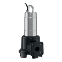
6.5.3 Connection of the single-phase AC motor
U1/Z1
bn
U2
bu
C
r
M 1~
gn-ye
LNPE
Fig.8: Connection diagram of the single-phase AC motor
Wire color Terminal
Brown (bn) L
Blue (bu) N
Green/yellow (gn-
ye)
Ground
The single-phase version is equipped with a shockproof
plug. The connection to the mains is established by in-
serting the plug into a socket. The plug is not over-
flow-proof. Install the socket in an overflow-proof
manner! Observe information on the protection class
(IP) of the plug.
DANGER!If the pump is connected directly to the
switchgear, remove the plug and have the electrical
connection carried out by a qualified electrician!
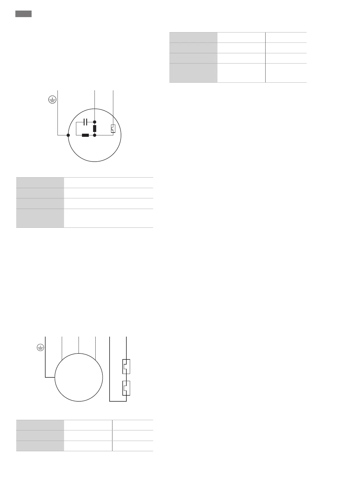
6.5.4 Connection of the three-phase current motor
W
5
1
2
V
4
U
3
M 3~
gn-ye
L3L2 2120L1PE
250 V (AC); 2,5 A; cos φ = 1
Fig.9: Connection diagram of the three-phase current motor
Wire number Designation Terminal
1 20 WSK
2 21 WSK
3 U L1
4 V L2
5 W L3
Green/yellow (gn-
ye)
Ground PE
For three-phase AC motors, a clockwise rotating field
must be present. The three-phase version is equipped
with a CEE plug or with bare cable ends:
▪If a CEE plug is present, the connection to the mains is
established by inserting the plug into the socket. The
plug is not overflow-proof. Install the socket in an
overflow-proof manner! Observe information on the
protection class (IP) of the plug.
▪If a bare cable end is present, the pump must be di-
rectly connected to the switchgear. DANGER!If the
pump is connected directly to the switchgear, have
the electrical connection carried out by a qualified
electrician!
6.5.5 Connection of the monitoring devices
All monitoring devices must be connected!
6.5.5.1 Monitoring the motor winding
Single phase AC motor
For AC motors the thermal motor monitoring is auto-
switching. The monitoring function is always active and
does not need to be connected separately.
Three phase AC motor with bimetallic strip
Bimetallic strips are connected in the switchgear di-
rectly or via an evaluation relay.
Connection values: max. 250V(AC), 2.5A, cos φ =1
When the threshold is reached, a deactivation must
take place.
For the version with an attached plug, the thermal mo-
tor monitoring in the plug is prewired and set to the
correct value.
6.5.6 Adjustment of the motor protection
The motor protection must be set depending on the
selected activation type.
6.5.6.1 Direct start-up
At full load, set the motor protection switch to the
rated current (see rating plate). At partial load, it is rec-
ommended to set the motor protection switch to 5%
above the measured current in the duty point.
6.5.6.2 Soft starter
At full load, set the motor protection switch to the
rated current (see rating plate). At partial load, it is rec-
 Loading...