Installation and operating instructions WILO Mather and Platt – VT pumps 29
8.7 Alignment of the pumps and its driving units
• When the sole plate is leveled and the satisfactory alignment
is completed, proceed with connection of suction & delivery
piping. Recheck the alignment after piping and run the final
grout beneath the base plate. Allow minimum seven days’
time for curing. Grout mix in the proportion specified earlier
for foundation bolt grouting should be used. It is further
recommended that all hollow pockets in the base plate shall
be filled after curing of earlier grout.
• The following procedures outline recommended practice
given in BS-3170 in 1972 (Appendix A) for checking shaft
alignment. This method is independent of the truth of the
coupling or shaft and is therefore not affected by canted
coupling faces or eccentricity of the outside diameter of the
coupling. Before commencing the alignment, rotate each
shaft independently to check that the bearings run freely and
that the shaft is true to 0.1mm or better. Check that no
damage can be caused when the shaft of the driven unit is
turned. Coupling should be loosely coupled, and the halves
must be free to move relative to each other, otherwise
Indicators can be incorrect. Where, tightly fitting pins gauge
or spring prevent loose coupling, the springs or pins should
be removed, a line scribed across both half couplings and
readings taken only when the two marks are aligned.
Angular alignment
• After isolating the driven unit from its power supply, clamp
two dial indicators are dramatically opposite points on one
half coupling or to the shaft behind it with the plunger resting
on the back of the other half coupling as shown in (Fig. 9 Pg.
No. 7) Rotate the coupling unit the gauges are in line
vertically and set the dial to read zero. Rotate the coupling by
180° and record the readings on each gauge. The readings
should be identical, though not necessarily zero. Either
positive or negative readings are acceptable provided they
are equally positive or negative. Adjust the position of one of
the units if necessary. Rotate the couplings unit the gauges
are in the line horizontally and adjust the dial to zero. Repeat
the operation outlined above by rotating the coupling by
180°. In case where fitment of dial gauge is not feasible check
gap between two coupling halves with the help of filler
gauge.
Radial alignment
• Clamp a dial gauge on one of the couplings or to the shaft as
shown in (figure 9 Pg. No. 7), with the plunger resting on the
rim of the other half coupling. Set the dial zero. Rotate the
coupling and note the reading at each quarter revolution. Any
variation in the readings indicates the deviation from
alignment and the position of one of the units must be
adjusted until the readings at each quarter revolution are
identical or within the tolerances given below.
CAUTION! Risk of material damage!
Oil level in reservoir to be checked and maintained
regularly to prevent damage to line shaft and bowl bush
bearing.
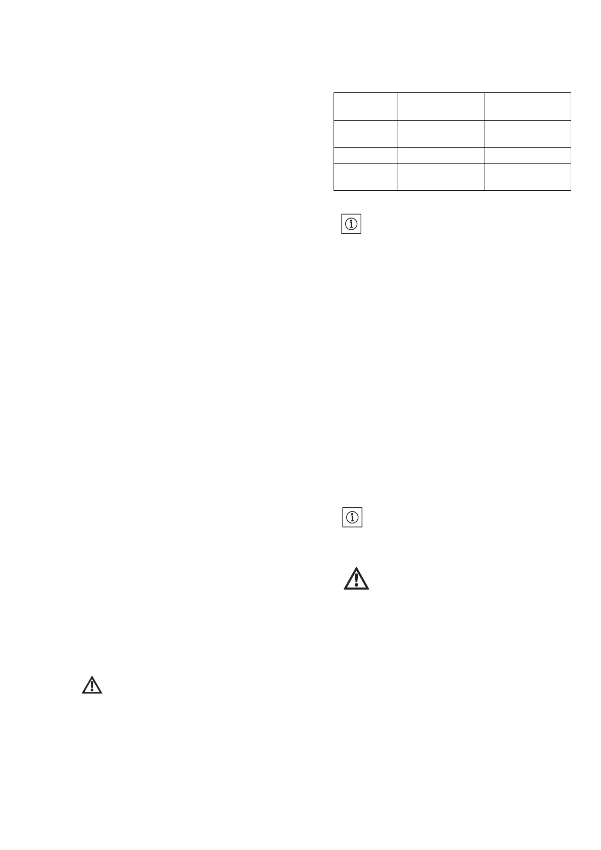
Alignment Tolerances:
TIR- Total Indicated Reading
NOTE:
All the alignments (angular as well as radial) have to be
carried out by using 3 dial indicators simultaneous
8.8 Forced water and oil lubricated pump pre checks
• In case of forced water lubricated pump start the booster
pumps initially to fill in the shaft tubes prior of starting the main
pumps. Check the regulated pressure at both shaft tube and
thrust bearing cooling inlet end. Suitable throttling should be
carried out before providing the supply for bearing cooling.
• Potable or fresh water should be used. If dirty water or raw
water from pump delivery is to be used special self-cleaning
strainers and pressure filters should be employed. A sufficient
size overhead tank should be selected for supplying of potable
water. Level switches should be employed to prevent water in
tank from falling below low level, thus preventing the system
from breakdown.
• In case of oil lubricated pumps, oil should be filled till top of the
shaft tube priorly before starting of main water pumps. A
reservoir of suitable size is provided which should be mounted
firmly to motor stool with the help of bracket. Oil flow to shaft
tube and level in reservoir is regulated with the help of an
automatic solenoid valve. Care to taken to only use bronze
bearing bushes in oil lubricated pumps. (Refer Fig. 21, Pg. No.
14)
NOTE:
Always refer forced water schematic provided by pump
manufacturer. (Fig 22 Pg. No. 14)
CAUTION! Risk
of
material
damage!
Oil level in reservoir to be checked and maintained
regularly to prevent damage to line shaft and bowl bush
bearing.