EasyManua.ls Logo

Wilo VT - Page 30

Wilo VT
56 pages
Print Icon
To Next Page IconTo Next Page
To Previous Page IconTo Previous Page
Loading...
Installation and operating instructions WILO Mather and Platt – VT pumps 30
MAXIMUM ALLOWABLE FORCES AND MOMENTS ON VT PUMPS
Forces (N) and Moments (N-m)
8.9 Pipe work
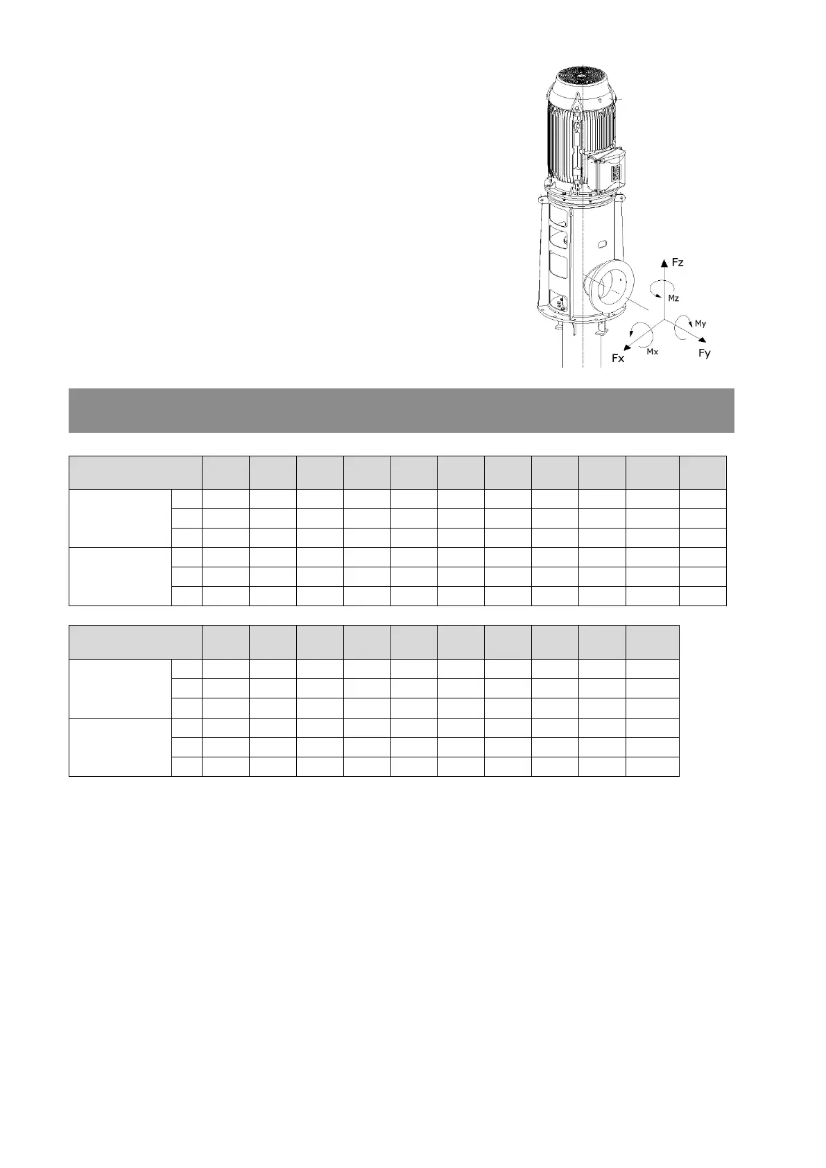
No stress must be imposed on the pump on delivery side by the pipe
work; neither by the weight of the pipes nor by the tightening of badly
fitting pipes (Refer Fig: 5). All pipe worked attached to the pump must
be fully supported and the mating faces of the pipe flanges must be
parallel and all bolt holes coinciding with each other. (See table of
maximum forces on flanges) It is important; therefore, that alignment
of the pump and motor should be rechecked after the pipes are finally
fitted. Resetting or supporting the pipes must correct any deviation in
the alignment.
Flange Nozzle size
[mm]
100
150
200
250
300
350
400
450
500
600
700
Forces
[N]
Fx
1427
2497
3790
5350
6688
7134
8472
9364
10032
11370
12374
Fy
1784
3121
4905
6688
8026
8918
10255
11147
12262
13823
15160
Fz
1248
2051
3121
4459
5350
5796
6688
7358
7914
9029
9810
Moments
[Nm]
Mx
1331
2309
3532
5027
6114
6386
5338
7744
8016
8424
8968
My
679
1182
1766
2445
2990
3125
3668
3940
4212
4415
4823
Mz
1005
1766
2581
3804
4620
4755
5434
5774
6114
6453
6793
Flange Nozzle size
[mm]
800
900
1000
1100
1200
1400
1500
1600
1800
2000
Forces
[N]
Fx
12819
13154
13622
14135
14648
15529
15716
15892
16285
147058
Fy
16052
16388
16989
17591
18237
19365
19600
15127
15784
20797
Fz
10255
10701
11415
12195
12998
14489
14803
19836
20307
16500
Moments
[Nm]
Mx
9511
10054
10659
11297
11970
13194
13450
13587
14254
14823
My
4959
5163
5523
5903
3611
7053
7210
7377
7711
8064
Mz
6997
7337
7805
8308
8838
9800
10006
10222
10644
11095

Related product manuals