8| P a g e
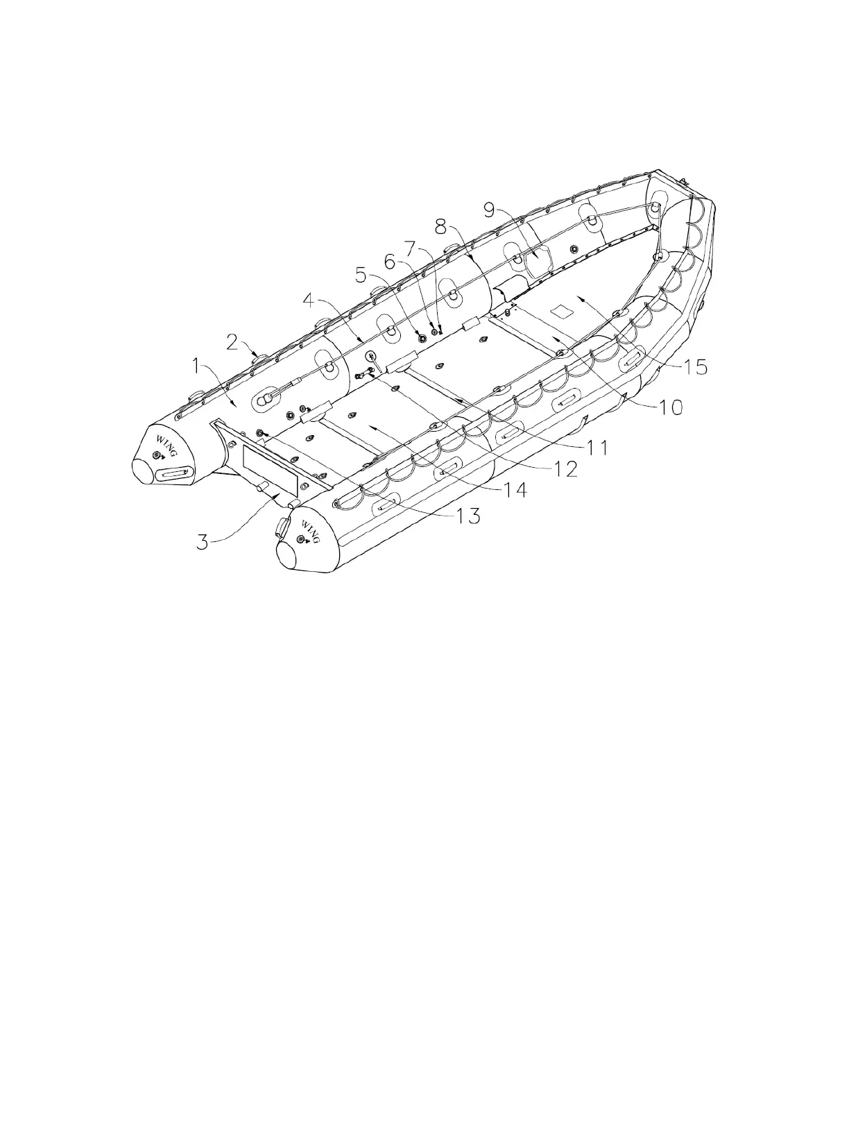
General CRRC Parts Diagram
1. Main Buoyancy Tube (MBT) – Primary inflatable structure of CRRC
2. Lifting Handle – Heavy duty handle placed on the outside of the MBT to enable the craft to be carried
3. Transom – Composite Structural beam at the stern on which an engine can be mounted
4. Inboard Lifeline – Line attached inboard on MBT
5. PRV – Pressure release valve
6. Fill Valve – Manual inflation valve
7. Fill Valve Cap – Protective cover for fill valve/redundant air seal
8. Seam Tape – 1” of Polyurethane material laid over welded seams
9. Paddle Holders – Secure paddles to MBT (certain models)
10. Main Thrust-board – FRP composite board near bow affords longitudinal support and provides attachment and
hoisting platform.
11. Floorboard Joiner – Aluminum extrusion mating two floorboards together
12. Air Chamber Crossover Valve For Single Point Inflation – Bypasses MBT baffle
13. Auto-Inflation Port – Valve where hose from inflation cylinder plugs into tube
14. Composite Hard Deck Floorboard – Creates hard deck surface (Number of floorboards depends on CRRC)
15. Bow Skirt – Protective laced in cover
 Loading...