Marine Installation Manual 2022-03 4-44
4 Ancillary Systems
4.5 Fuel gas system
X62DF-S2.0
Free-standing –
Type A tank
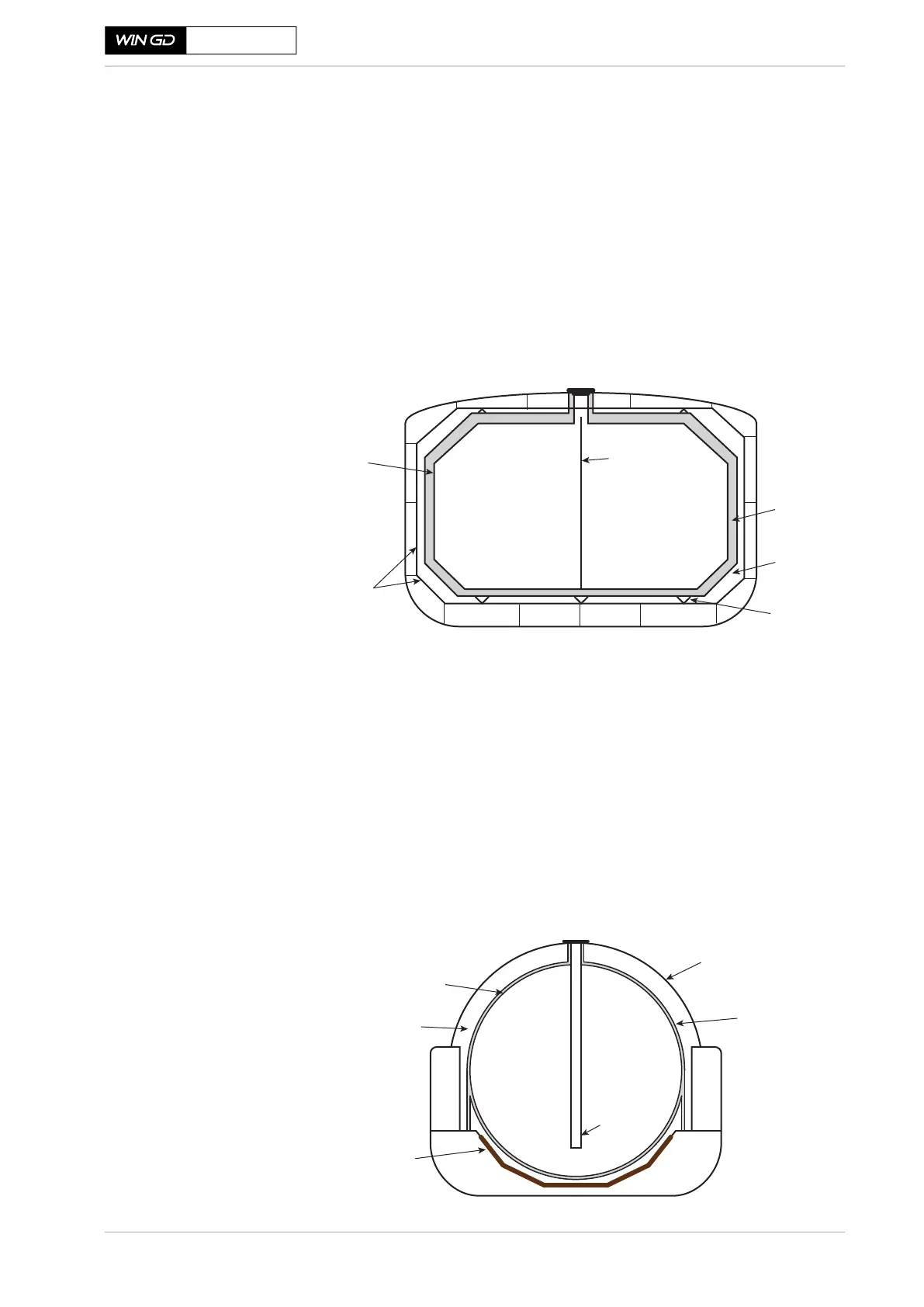
As specified by the IGC Codes, the Type A tank must have a second barrier to
withhold leaks. Often the ship hull is used as this second layer, so to maximise
volume efficiency, the tank is designed in a prismatic shape to best fit inside the
vessels hull. Between the tank wall and secondary barrier is a solid insulation
layer and an air-gap layer. This reduces the thermal impact on the LNG from the
environment, therefore reducing the BOG. This gap also allows for a given ex-
pansion of the tank wall, which is a result of the Type A tank design. The tank
adjusts to the gas pressure due to its flexible structure. Therefore, it is very impor-
tant to control the pressure increase, which must remain within a very limited
pressure range (defined as non-pressurised tank), as otherwise structural dam-
ages would occur.
Figure 4-26 Section view of a free-standing Type A tank
Free-standing –
Type B tank
Same as the Type A tank, the Type B tank is also designed to be non-pressurised
and will respond to pressure increase by expansion. Consequently, it is also as
important to control the pressure increase. The Type B tank design is based on a
fail-safe concept. From crack monitoring and analysis, the ‘Leak before Failure’
approach of this design means that fatigue is progressive and not catastrophic.
Therefore, it is only necessary to have a partial secondary barrier to hold the cal-
culated maximum leakage. In the past, the Type B tank, referred to as the Moss
type (see Figure 4-27), was spherical. This curve-designed shape supports the
even distribution of stress across the tank walls. Nowadays however, the Type B
tank (same as the Type A tank) is also available in a prismatic shape, having a
partial secondary barrier.
Figure 4-27 Section view of a free-standing Type B tank of moss design
SM-0741
Primary
barrier
Secondary
barrier
Insulation
Bulkhead
Inspection
space
Support
SM-0742
Primary
barrier
Drip-tray for
detection leakage
External
insulation
Weather protective
cover
Support tube
for access
Air-gap