Marine Installation Manual 2022-03 4-15
4 Ancillary Systems
4.3 Cooling water system
X62DF-S2.0
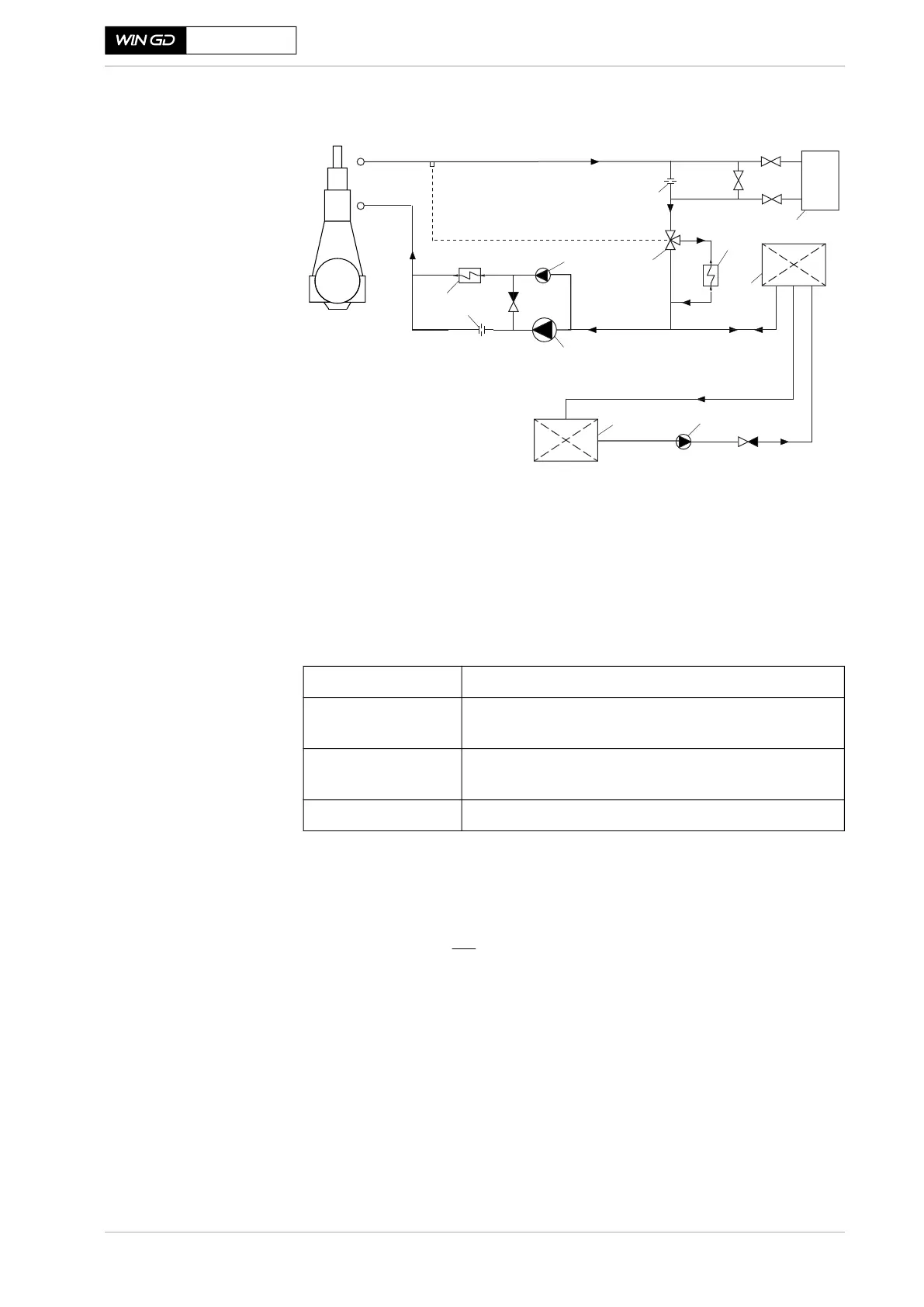
Figure 4-11 HT cooling water circuit
High-temperature circuit components
HT cooling water pump
SM-0321
Main
Engine
3
9
2
1
6
6
8
7
10
4
5
1 HT Pumps
2 Pre-heater pump (optional)
3 Pre-heater for ME
4 HT Cooler (HTC)
5 Automatic temp. control valve
6 Throttling disc
7 Freshwater generator
8 HT Circuit buffer unit
9 Buffer unit supply pump
10 CW feed & drain tank
Pump type Centrifugal, preferably with a steep head curve
a)
a) As a guide, the minimum advisable curve steepness can be defined as follows:
For a pressure increase from 100 to 107 %, the pump capacity should not decrease by more than
10 %.
Pump capacity According to GTD: The flow capacity is to be within a tolerance
of - 10 to +20% of the GTD value
Delivery head
b)
b) The pump delivery head (p
p
) will be:
[bar]
where:
p
ei
= pressure at engine inlet [bar]
p
st
= static pressure* at pump inlet [bar]
Δ
p = pressure losses over piping between pump outlet and engine inlet [bar]
h = height difference between pump outlet and engine inlet [m]
* If an expansion tank is used, p
st
equals the static pressure head from the change in height between
expansion tank and pump inlet.
If a buffer unit is used, p
st
equals the buffer unit pressure plus the pressure head from the change
in height between buffer unit and pump inlet.
The pressure (p
ei
) at engine inlet must be 3.0-5.0bar(g).
To be determined according to the total pressure losses (resist-
ance) of the actual piping installation arrangement
Working temperature 95 °C