Marine Installation Manual 2022-03 2-10
2 Engine Power and Speed
2.6 Power range limits with a power take-off installation for a FPP
X62DF-S2.0
2.6 Power range limits with a power take-off installa-
tion for a FPP
A main engine-driven generator is named as a Power Take-Off (PTO), as its
driving power is provided by the main engine. The addition of a PTO installation
alters the working range and operating characteristics of the engine. Two
methods of incorporating the PTO are outlined in the following sections.
WinGD recommends to follow Method 1.
PTO considerations
• The PTO is used for generating the navigation electric power
• The PTO is connected with a frequency converter system
• The PTO is not engaged in heavy sea conditions
• Mechanical power absorption of the PTO must be considered
PTO incorporation of Method 1
CMCR - Method 1
This first method considers the PTO as an addition to the previously defined pro-
peller power requirements, therefore increasing the CMCR of the engine.
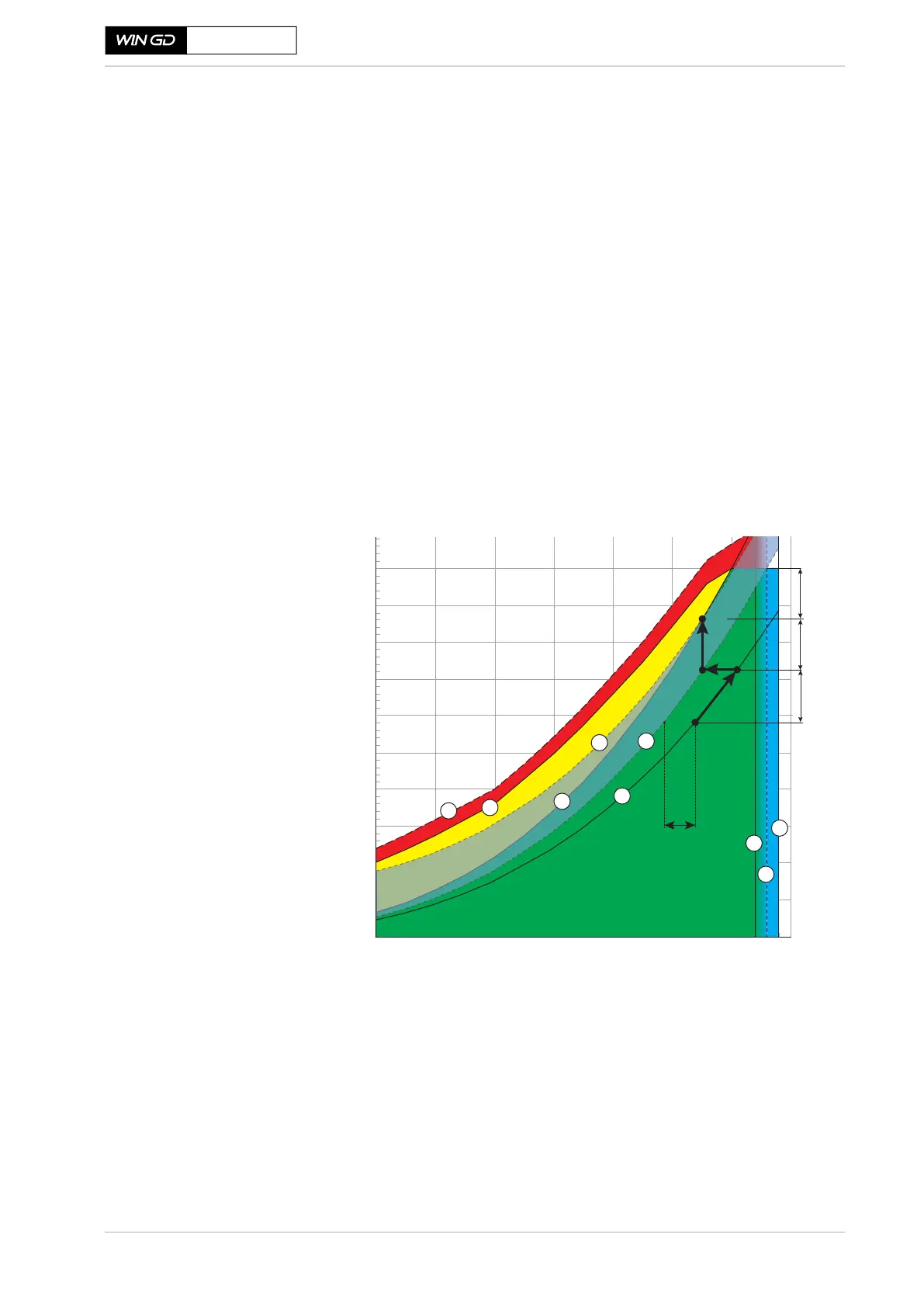
Figure 2-4 Power range diagram of an engine with a PTO
Line 7a in Figure 2-4 shows the power required for the propeller, where Line 7b
shows the power needed for the propeller combined with a constant power re-
quirement from the PTO .
SM-0029
(Line 7) = Nominal engine characteristic
(Line 7a) = Nominal propeller characteristic without PTO
(Line 7b) = Nominal propeller characteristic with PTO
0
10
20
30
40
50
60
70
80
90
100
40 50 60 70 80 90 100 110
Engine speed [% Rx]
Engine power [% Rx]
8
7
6
5
4
3
3a
7b
7a
LR margin
EM
PTO
SM
B
B’
A
Point A = Light running in ideal sea conditions (sea trial)
Point B = CSR
Point B’ = Continuous service without PTO power