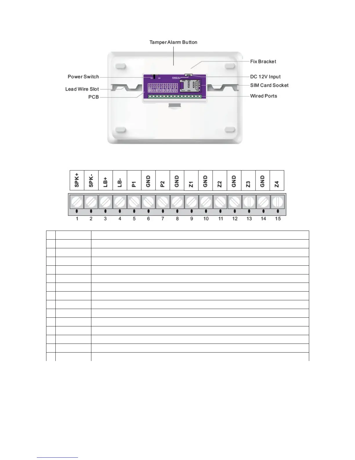
Alarm Panel back schematic diagram:
Wired terminal block:
1 SPK+ Positive of siren (red cable)
2 SPK- Negative of siren (black cable)
3 LB+ Positive of two-way speaker (red cable)
4 LB- Negative of two-way speaker (black cable)
5 P1 12V output by remote control. (please refer to Operation Instruction part)
6 GND Ground
7 P2 Linkage output port 2. Supply12V output once the system is armed, and be off once it’s disarmed
8 GND Ground
9 Z1 Wired sensor 1 (zone number: 95)
10 GND Ground
11 Z2 Wired sensor 2 (zone number: 96)
12 GND Ground
13 Z3 Wired sensor 3 (zone number: 97)
14 GND Ground
15 Z4 Wired sensor 4 (zone number: 98)
VERY IMPORTANT – bigger sirens
Do not add a bigger siren than supplied directly to the alarm unit. A bigger siren can be added via a
suitable relay unit, please contact your supplier for more information. A bigger siren will overheat
some components (not maybe but surly) and destroy them. Such action will void product
Guarantee.
Page 7 Wolf Secure http://www.wolfsecure-gsmalarms.co.za

 Loading...