74 3064810_201804
37.Technicalinformation,air/uegas
routing
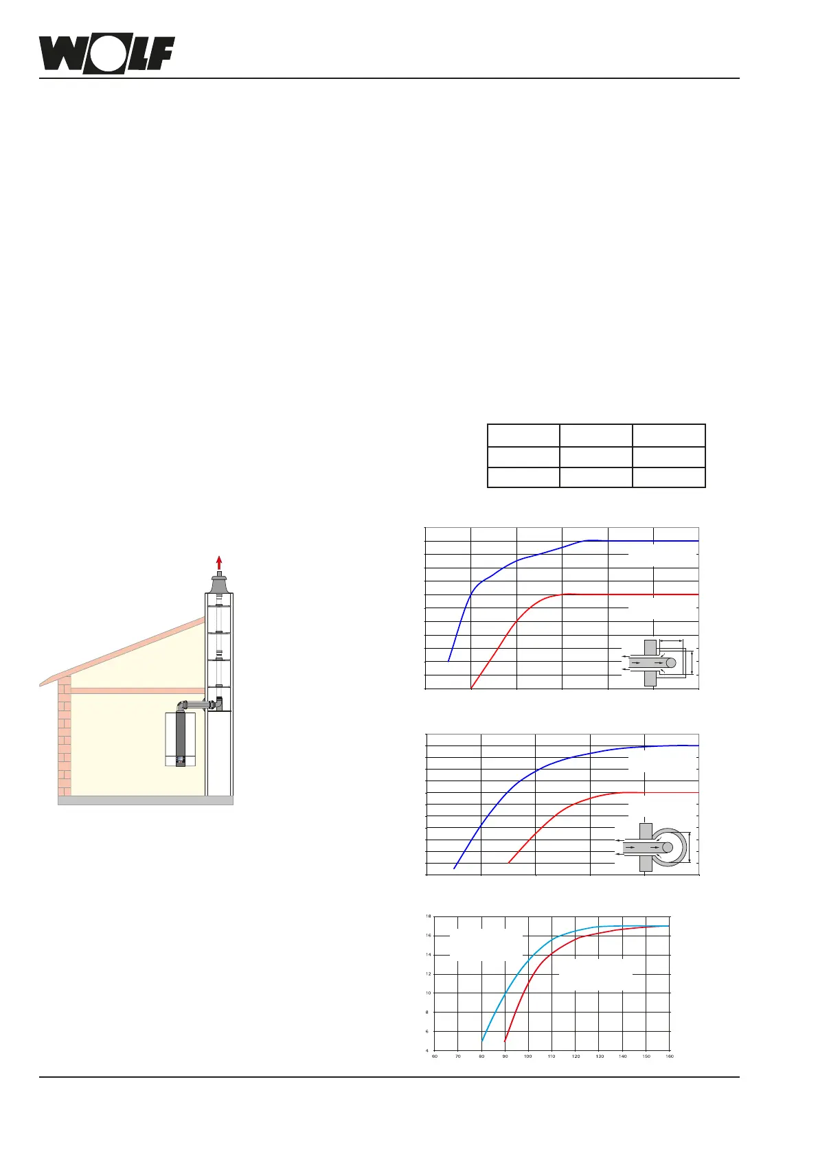
Ifthegascondensingboilerisinstalledwithabalancedueroutedoveranexternalwall
(type C13x), the rated boiler output in heating mode must be reduced to below 11 kW
(for appropriate measures, see chapter "Limiting the maximum output").
Itmustbepossibletoinspecttheentirecross-sectionoftheues.Therefore,installan
appropriate cleaning and/or inspection aperture inside the boiler room; agree suitable
arrangementswithyourlocaluegasinspector.
Flue connections are created using couplings and gaskets. Always arrange couplings
againstthedirectionofthecondensateow.Installthebalanceduewithaslope
ofatleast3°towardsthegascondensingboiler.Installspacerclampstosecure
thepositioning(seeinstallationexamples).
Connectiontothebalancedue
Thecalculatedlengthofthebalanceduesystemortheueisderivedfromthestraight
pipe length and the length of any pipe bends.
Example for a 60/100 system
1)
:
Straight balanced ue pipe, length 1.5 m L = straight length + bend length
1 x 87° bend ≙ 1.5 m
L = 1.5 m + 1 x 1.5 m + 2 x 1.3 m
2 x 45° bends ≙ 2 x 1.3 m L = 5.6 m
Calculatingthe
balanceduelength
Note: Toavoidreciprocalinterferencebetweenairanduegaspipesroutedabove
the roof, we recommend maintaining a minimum clearance of 2.5 m between
the pipes.
1)
Equivalent length of the system:
60/100 80/125
87° bend 1.5 m 3 m
45° bend 1.3 m 1.5 m
MinimumductsizeforroomsealedoperationC93x
Assuming: In the installation room:
2x inspection bends, 1x 87° bend and
1.5 m horizontal with 87° support bend
C93x
Flue pipe DN 80
8
9
10
11
12
13
14
15
16
17
18
19
20
100 110 120 130 140 150 160
Square duct [mm]
Connecting pipe
DN 60/100
Connecting pipe
DN 80/125
Max. vertical length [m]
a
8
9
10
11
12
13
14
15
16
17
18
19
20
110 120 130 140 150 160
Connecting pipe
DN 60/100
Connecting pipe
DN 80/125
Round duct [mm]
Max. vertical length [m]
Flue pipe DN 80
Max. duct length in [m]
Duct cross-section in [mm]
Connecting pipe
DN 60/100
round
Connecting pipe
DN 60/100
square
Flue pipe DN 60