82 3064810_201804
37.Technicalinformation,air/uegas
routing
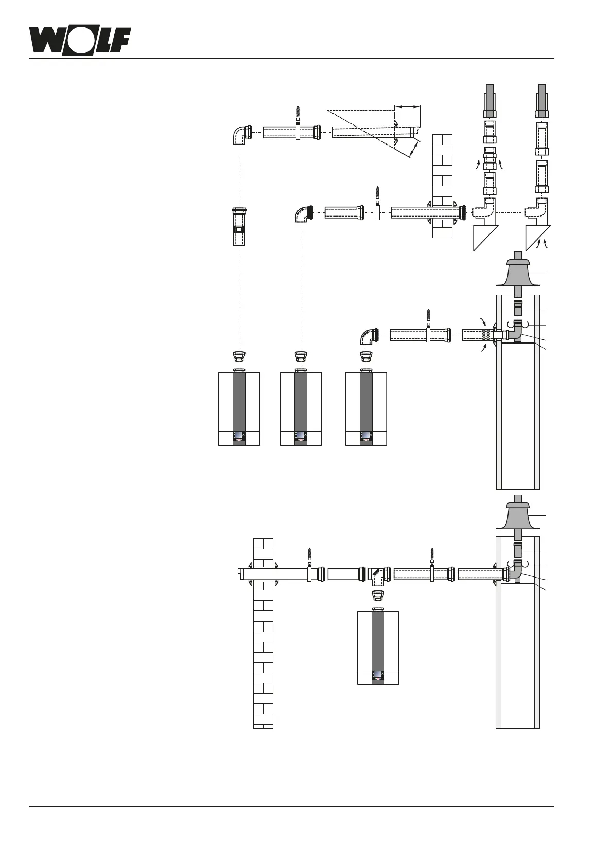
Concentricbalancedue,horizontalC13x,C83xandB33
andueonanexternalwallC53x(examples)DN80/125
1621
4
5
45
4
16 16
22
15 16
220
>400
3
11
45
2
10
10
17
18
20
18
17
18
19
20
18
1 1 1
Horizontalbalanceduerouted
through pitched roof
Flue routed along external wall
(only where required)
Recess Ø 90 mm in
chimney side. Install the
uepipeairtightintothe
chimney side.
C13x C53x B33
Dormer
1 Gascondensingboiler
2 Adaptor DN60/100
to DN80/125
3 Balanceduepipewithinspec-
tion port DN80/125
(250 mm long)
4 BalanceduepipeDN80/125
500 mm
1000 mm
2000 mm
5 Spacerbracket
10 Inspectionbend87°DN80/125
11 Bend 87° DN 80/125
15 Balanceduepipe
horizontal, with wind protector
16 Pipe collar
17 External wall panel 87° DN80/125
with smooth air pipe end
18 Balanceduepipe,
externalwalls
DN80/125
19 Airinlet,externalwall
DN80/125
20 Conc. outlet terminal
withclamptting
21 Connection to a
uegaschimneyB33
Length 250 mm with air aperture
22 Support rail
23 Support bend 87° DN80
24 Spacer
25 PPuepipeDN80
26 Ductcover with
UV resistant terminal
28 Inspectiontee
29 Air pipe Ø 125 mm
30 Air inlet pipe Ø 125 mm
Installthehorizontaluepipewithaslopeofapprox.3°(6cm/m)towardstheboiler.
Routethehorizontalairsupplywitha3°slopetowardstheoutside–ttheairinletwith
a wind protector; permissible wind pressure at the air inlet 90 Pa. The burner will not
startifthewindpressureishigher.Downstreamofsupportbend(23),theuecanbe
routedinDN80insidetheduct.AexibleuepipeDN83canbeconnecteddownstream
of support bend (23).
16 16 4552930
28
2
4
16
1
C83x