84 3064810_201804
37.Technicalinformation,air/uegas
routing
Maintain the following clearance between the internal duct wall and
theue: forroundducts: 3cm
for square ducts: 2 cm
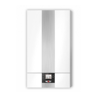
1 Gascondensingboiler
2 Adaptor DN60/100
to DN80/125
16 Pipe collar
22 Support rail
23 Support bend 87° DN80
24 Spacer
25 PPuepipeDN80
26 Ductcover with
UV resistant terminal
31 Balanceduedistributor
80/80 mm
32 Air inlet pipe Ø 125 mm
33 Bend 90° DN80
34 87° tee with
inspectionportDN80
35 Flue pipe DN80
500 mm
1000 mm
2000 mm
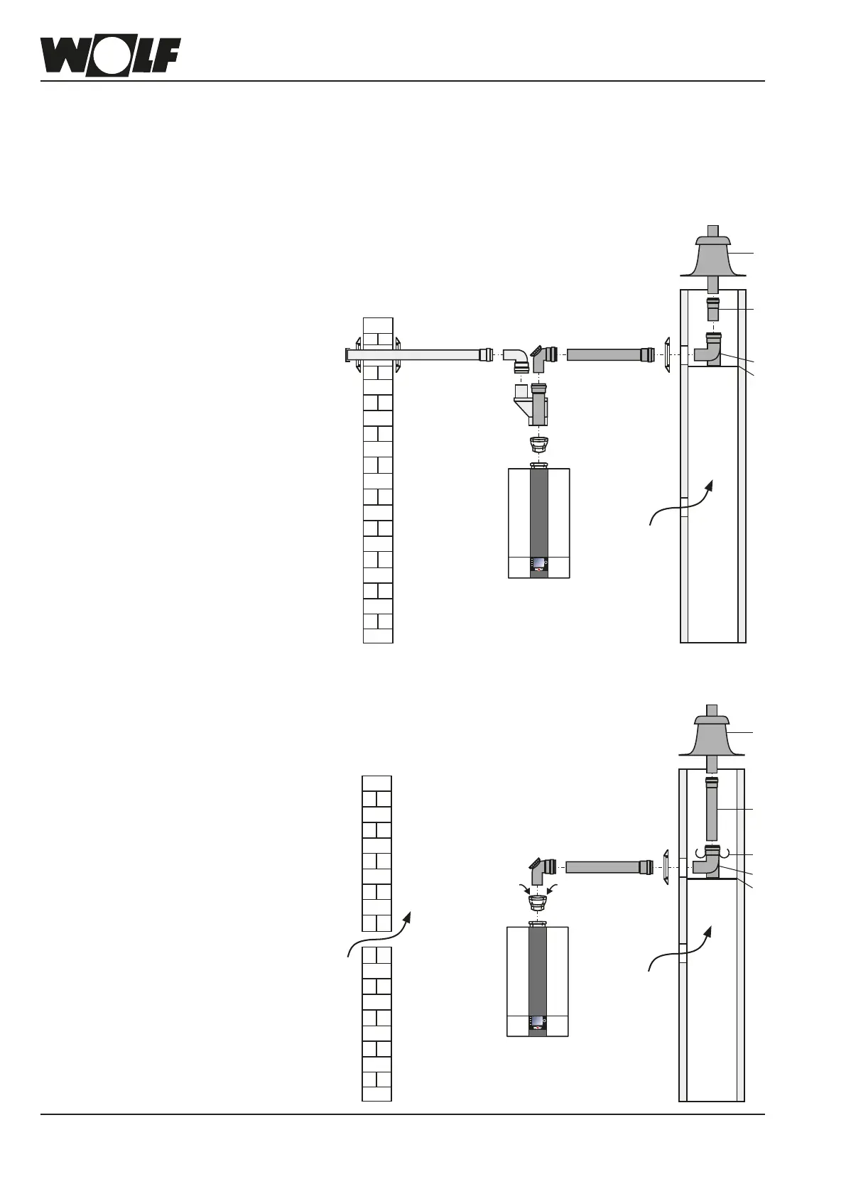
Installeccentricbalanceduedistributor80/80mm(31)forseparateairsupply/uegas
routing downstream of connection adaptor DN80/125 (2) with a test connector.
Whenconnectingabalanceduecertiedacc.toBuildingRegulations,observethe
permit of the relevant body.
Installthehorizontaluepipewithaslopeofapprox.3°(6cm/m)towardstheboiler.
Routethehorizontalairsupplywitha3°slopetowardstheoutside–ttheairinletwith
a wind protector; permissible wind pressure at the air inlet 90 Pa. The burner will not
start if the wind pressure is higher.
Eccentricbalancedue
2
34 25 16
Secondary
ventilation
C53
2
31
33 3432 25 161616
22
23
25
26
1
Secondary
ventilation
C53