26
3064458_201811
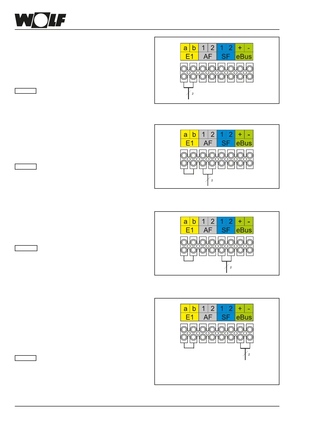
Connecting input E1
Route the power cable through the cable entry and secure it
in the control unit using a cable tie. Isolate jumper at input E1.
Connect the connection cable for input E1 to terminals E1 as
shown in the wiring diagram.
No external voltage may be connected to in-
put E1, as this could destroy the component.
Please note
Fig: Connecting input E1
Low voltage appliance connections
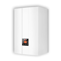
Connecting the outside temperature sensor
Insert and secure the connecting cable through the cable
entry. The outside sensor can be connected to the terminal
strip of the condensing boiler at connection AF, or to the
terminal strip of the control accessories.
When installing the appliance in places
where there is a risk of high electromagnetic
interference, it is advisable to t shielded
sensor and eBUS cables. The cable shield
should be connected at one end to the PE
potential in the control unit.
Please note
Fig: Connecting the outside temperature sensor
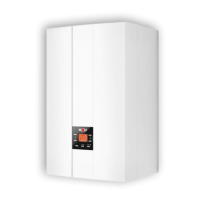
Connecting the cylinder sensor
Insert and secure the connecting cable through the cable en-
try. Connect the connection cable for cylinder sensor SF to the
SF terminals as shown in the wiring diagram.
When installing the appliance in places where
there is a risk of high electromagnetic interfer-
ence, it is advisable to t shielded sensor and
eBUS cables. The cable shield should be
connected at one end to the PE potential in
the control unit.
Please note
Fig: Connecting the cylinder sensor
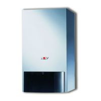
Connecting digital Wolf control accessories
(e.g. BM-2, MM, KM, SM1, SM2, ISM7e)
Only connect control units from the Wolf accessory range.
Each accessory is supplied with its own connection diagram.
Use a two-core cable (cross-section > 0.5 mm²) as the
connecting cable between the control unit accessory and the
condensing boiler.
When installing the appliance in places
where there is a risk of high electromagnetic
interference, it is advisable to t shielded
sensor and eBUS cables. The cable shield
should be connected at one end to the PE
potential in the control unit.
Please note
Fig: Connecting digital Wolf control accessories (eBUS interface)
14. Electrical connection
Please note: Observe
+/- polarity