Installation
6720813171 (2015/04)26
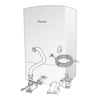
8.5.2 Terminal strip connections
▶ Turn the vent key through a quarter rotation to undo the boiler door
lock ( fig. 38, see detailed picture).
▶ Push the fastener down ( fig. 38) and open the boiler door.
Fig. 38 Open the boiler door
▶ Undo 1 screw to release the cover over the electrical connections
and pull the cover upwards ( fig. 39).
Fig. 39 Pull up the cover over the electrical connections
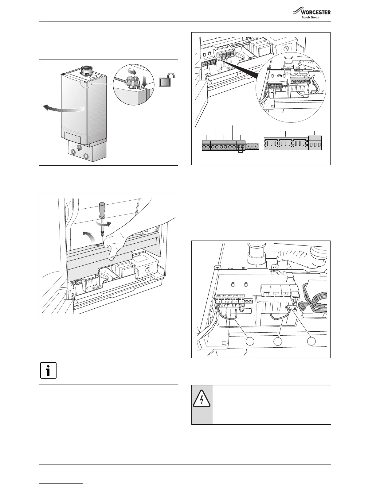
The terminal strip in the boiler ( fig. 40) has a number of terminals to
connect internal and external electrical components. The listing below
shows which components must be connected to which terminals
( section 7.5.4, page 36).
Fig. 40 Terminal strip
[A] Low-voltage connections
[B] 230 V connections
8.5.3 Routing the cable through the boiler
▶ Route the cable for the low-voltage connections through the hole on
the left [1].
▶ Route the cable for the 230 V-connections through the hole on the
right [2].
▶ Attach the cable for the 230 V-connections using the strain relief
clamps [3].
Fig. 41 Routing the cable
8.5.4 Description of the terminal strip connections
▶ Connect all components to the relevant terminals.
If uncertain how to connect controls to this appliance,
first contact the Worcester technical helpline on
0330 123 3366 or your supplier.
DANGER: Danger of fatal accident due to electric shock.
Items 1 – 6 are low-voltage connections and items
7 – 10 are 230 V-connections ( fig. 42).
▶ Please be aware that there may be a voltage on items
7 – 10 (230 V), when power is supplied to the boiler.

 Loading...