Commissioning
6720813171 (2015/04) 43
10.2.9 Measuring the flue gases CO
2
emissions
▶ Open at least 2 thermostatic radiator valves. Do not switch on the
boiler.
▶ Push on the control panel to open it ( fig. 68, page 32).
▶ Switch off the heating system by pressing the mains switch of the
BC10 basic controller ( fig. 90, [1]).
▶ Remove the cover from the flue gas measuring point [1].
▶ Connect the flue gas analyser to the left-hand measuring point.
Fig. 91 Measuring the gas supply pressure
▶ Switch on the heating system by pressing the mains switch of the
BC10 basic controller ( fig. 90, [1]).
▶ Press and hold the “Chimney sweep” button ( fig. 90, [3])
(approximately 2 seconds), until the dot in the right-hand bottom
corner of the display ( fig. 90, [9]) appears. See also table 10,
“Flue gas test”, page 34.
▶ After the “Burner” LED ( fig. 90, [6]) has lit up wait for one minute
until the boiler is burning at full load.
▶ Measure the carbon monoxide content at the flue gas measuring
point ( fig. 91).
The CO values in air-free condition must be less than 400 ppm or
0.04 vol. %. Values of 400 ppm or more indicate an incorrect burner
adjustment ( section 10.2.7, page 41), a dirty gas burner or heat
exchanger or burner faults.
▶ You must determine and remove the cause ( chapter 12,
page 46).
▶ Press the “Chimney sweep” button ( fig. 90, [3]) to clear the
reading. See also table 10, “Flue gas test”, page 34.
▶ Switch off the heating system by pressing the mains switch of the
BC10 basic controller ( fig. 90, [1]).
▶ Remove the flue gas analyser and fit the cover back onto the flue gas
measuring point ( fig. 91, [1]).
▶ Switch on the heating system by pressing the mains switch of the
BC10 basic controller ( fig. 90, [1]).
▶ Press on the control panel to close it ( fig. 95, page 45).
10.2.10 Carrying out a function test
▶ During initial start-up and annual inspection and/or needs-oriented
servicing, make sure that all control, regulating and safety devices
are in full working order and, if applicable, check them for correct
adjustment.
▶ The gas and water circuits must be tested for leaks
( sections 10.2.1 and 10.2.8).
10.2.11 Measuring the ionisation current
▶ Push on the control panel to open it ( fig. 68, page 32).
▶ Open at least 2 thermostatic radiator valves. Do not switch on the
boiler.
▶ Switch off the heating system by pressing the mains switch of the
BC10 basic controller (
fig. 90, [1]).
▶ Turn the vent key through a quarter rotation to undo the boiler door
lock ( fig. 71, see detailed picture, page 37).
▶ Push the fastener down and open the boiler door ( fig. 71,
page 37).
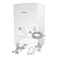
▶ Undo the plug and socket connection of the monitoring cable.
Fig. 92 Removing the ionisation electrode plug and socket connection
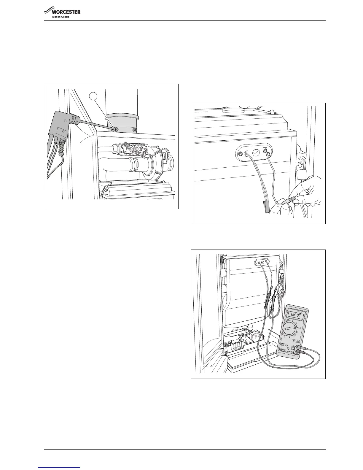
▶ Connect the multimeter in series. Select the μA DC range on the
multimeter. The multimeter must have a resolution of at least 1 μA.
Fig. 93 Measuring the ionisation current
▶ Switch on the heating system by pressing the mains switch of the
BC10 basic controller ( fig. 90, [1]).
▶ Activate the Service mode in accordance with the “Service mode”
menu ( table 11, page 34).
▶ Set the capacity to minimum (part load) according to the “Service
mode” menu ( table 11, page 34).
▶ After the “Burner” LED ( fig. 90, [6]) has lit up wait for one minute
until the boiler is burning at part load.

 Loading...