SERVICING
& SPARES
INSTALLATION & SERVICING INSTRUCTIONS
36
8 716 115 216b (09.2008)
INSPECTION AND SERVICE
INSPECTION AND SERVICE
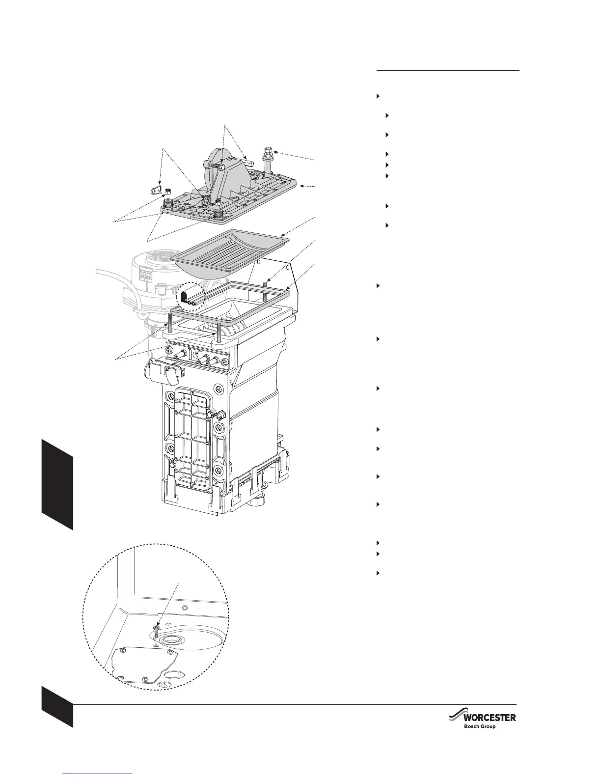
Burner:
Check that the boiler is completely isolated
from the gas supply.
1
Remove the clips (A), castellated nuts
(B1) and springs (B2) from the studs (B).
Unscrew and remove the two hexagon
headed screws (C) securing the fan.
Remove nut (D1) from the rear stud (D).
Remove the burner cover plate (E).
2
Remove the burner (F) and clean the
components.
Do not use a wire brush.
Re-assemble burner in reverse order
using a new seal (G).
After re-assembly check CO/CO2 levels
as described in the section “Setting the
air/gas ratio”
For sealed systems only:
Max pressure:
When the heating system water is at
maximum temperature, 2.65 bar must not
be exceeded. If this pressure is exceeded
then an extra expansion vessel must be
fitted into the system return as close as
possible to the appliance.
If the system does not retain the pressure,
the expansion vessel and the heating
system should be checked for leaks.
Electrical wiring:
Check the electrical wiring for physical
damage and replace any damaged wires.
To check the flap valve in fan intake:
Refer to page 38 for access to the fan
intake.
Carefully withdraw the flap valve from fan
intake tube and check for soiling and splits,
clean or replace as required.
Take care when refitting the flap valve, the
flaps must open upwards into the fan intake
tube.
After re-assembly check CO/CO2 levels
as described in the section “Setting the
air/gas ratio”
To clean the condensate trap:
Remove pipe from condensate pump.
Remove screw retaining trap (F) and push
trap downwards until clear.
Remove trap from boiler along with pipe
to condensate pump.
F
A
B1
C
D1
F
G
B
D
E
B2
 Loading...