PRE-INSTALLATION
Greenstar Highflow CDi
ErP
- 6720818077 (2016/04)16
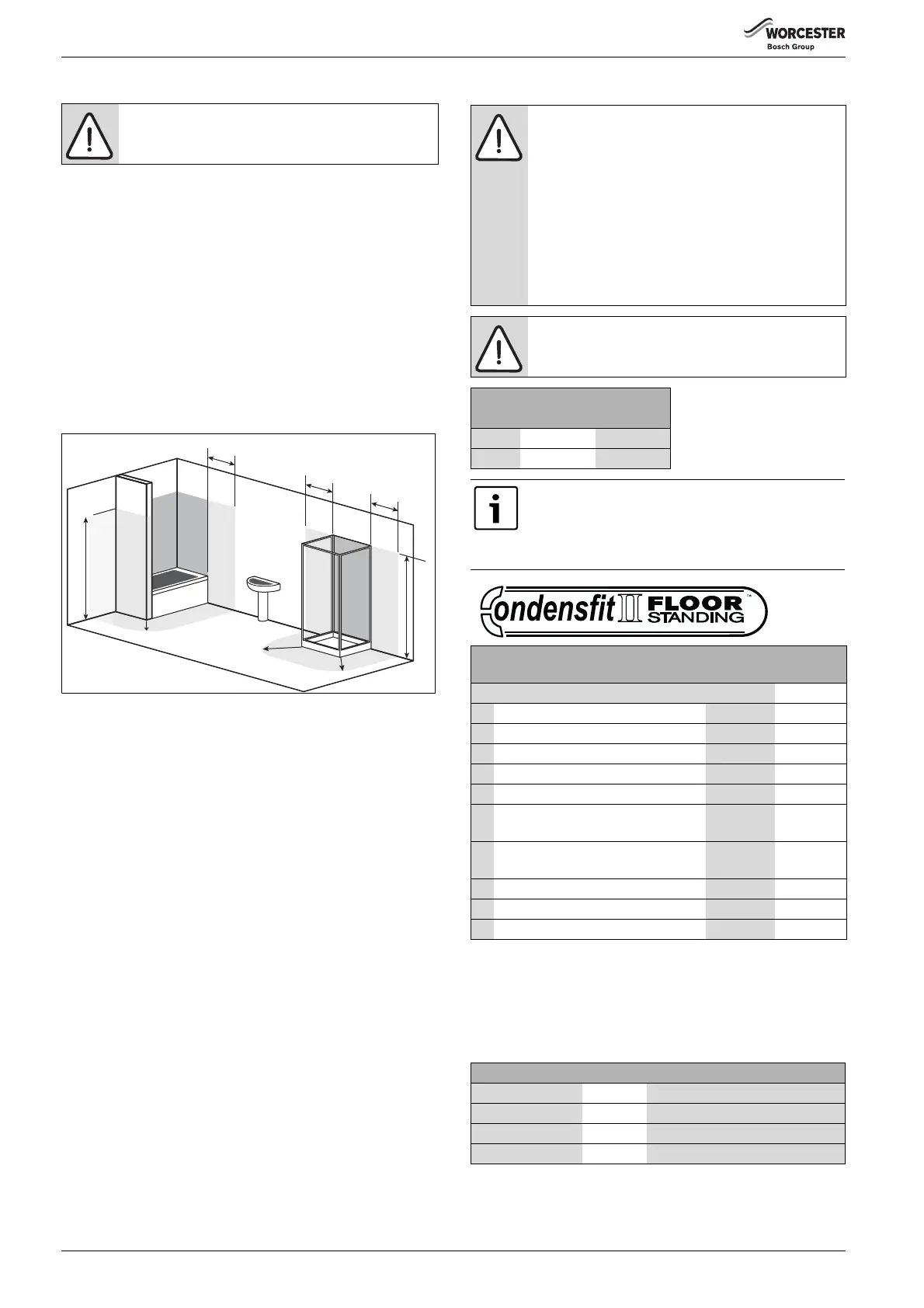
3.6.4 Rooms containing a bath or shower
An appliance fitted with a mechanical, RF mechanical timer, or a clip-in
weather compensating controller may be only installed outside the
shaded area.
An appliance fitted with a blanking panel or a timer/programmer
conforming to IP4XD can be installed in zone 2.
An appliance and programmer combination conforming to less than
IP4XD can only be installed outside the shaded area.
BS7671 Amendment 3:2015 requires a 30mA RCD (Residual Current
Device) for installations within this location as well as for any circuits
passing through zone 1 and/or 2 not serving this location.
If the appliance is installed into a cupboard that opens into zone 1 or 2 it
is strongly recommended that a 30mA RCD is fitted to the circuit
supplying the boiler.
Refer to the latest IET wiring regulations.
Fig. 15 Bathroom installations
[2*] Without the end wall, zone 2 must extend 600mm from the bath
3.7 Flue options
The flue systems have different maximum flue lengths.
The next page shows various flue options.
Refer to the flue options in table 9 for the straight flue lengths required
to achieve the maximum flue length.
NOTICE: Any switch or appliance control using mains
electricity must not be within reach of a person using the
bath or shower.
6720646608-124.4Wo
2*
*Radius 600mm
1
2
1
2
2
1
600mm
600mm
600mm
2250mm
2250mm
2*
*
*
*
CAUTION: Non accessible flue systems:
▶ Where a flue system is not going to be accessible,
provision must be made for service and inspection.
▶ Voids containing concealed flues must have at least
one inspection hatch no less than 300mm square.
▶ Flue joints within the void must not be more than 1.5
metres from the edge of the inspection hatch.
▶ Inspection hatches should be located at changes of
direction.
▶ If this is not possible, bends should be viewable from
both directions.
NOTICE: Effective flue lengths of bends:
Each bend used has an equivalent straight flue length
▶ refer to the table below
Effective flue length
Bend 60/100 80/125
45° 0.75m 1m
90° 1.5m 2m
Plume management kits are available for the 60/100
horizontal flue system,
Part number 7 716 191 086.
Refer to the manual supplied with the Plume
Management kits for complete installation instructions
Highflow CDi boilers
Maximum total flue
length L (mm)
FLUE TYPE 60/100 80/125
1 Telescopic horizontal flue assembly 140
1)
- 530
1) Flue is cut to a minimum of 130mm, flue connector adds the additional 10mm.
350 - 1,200
2 Horizontal flue extension 4,000 13,000
3 Horizontal flue with 1 x 90° bend 2,000 11,000
4 Horizontal flue with 2 x 90° bends N/A 9,000
5 High level horizontal flue 2,000 11,000
6 High level horizontal flue with 2 x 90°
bends
N/A 9,000
7 High level horizontal flue with 3 x 90°
bends
N/A 7,000
8 Vertical flue assembly 6,400 15,000
9 Vertical flue with 2 x 90° bends 2,400 11,000
10 Vertical flue with 2 x 45° bends 4,400 13,000
Table 9 Flue options
Part number Flue Description
7 716 191 155 60/100 Telescopic horizontal flue assembly
7 716 191 157 80/125 Telescopic horizontal flue assembly
7 716 191 156 60/100 Vertical flue assembly
7 716 191 158 80/125 Vertical flue assembly
Table 10 Flue options

 Loading...


