PRE-INSTALLATION
6720818077 (2016/04) - Greenstar Highflow CDi
ErP
19
3.9 Plume management terminal positions
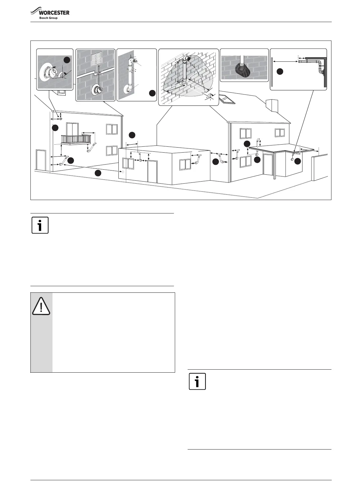
Fig. 17 Plume terminal positions
Key to illustration
1. This feature allows some basic plume re-direction options on a
standard telescopic horizontal flue terminal.
300mm minimum clearances to a opening e.g. window.
However the minimum clearances to an opening in the direction that
the plume management is facing, must be increased to 1,500mm.
Where the flue is less than 150mm to a drainpipe and plume re-
direction is used the deflector should not be directed towards the
drainpipe.
2. 300mm adjacent to a boundary line.
3. Plume Management kit air intake can be reduced to 150mm
providing the flue exhaust outlet is no less than 300mm adjacent to a
boundary line.
4. 1,200mm between terminals facing each other.
5. 600mm distance to a boundary line, unless it will cause a nuisance.
BS 5440:Part 1 recommends that care is taken when siting
terminal in relation to boundary lines.
6. Using a Plume Management kit the air intake measurement can be
reduced to 150mm providing the flue exhaust outlet has a 300mm
clearance.
Plume kits running horizontally must have at least a 3° fall back to
the boiler for proper disposal of condensate, except or the initial
horizontal run from the terminal (refer to note opposite).
For details on specific lengths see relevant boiler Technical and
Specification information.
7. Internal/external corners. The air intake clearance can be reduced
to 150mm providing the flue exhaust outlet has a 300mm
clearance.
8. Clearances no less than 200mm from the lowest point of the
balcony or overhang.
9. 1,200mm from an opening in a car port on the same wall e.g. door
or window leading into the dwelling.
10. 600mm distance to a surface facing a terminal, unless it will cause
a nuisance. BS 5440: Part 1 recommends that care is taken when
siting terminals in relation to surfaces facing a terminal.
200
300
150
200
8
4
5
3
2
9
200
600
All measurements in millimetres
300
300
150
150
300
300
25
25
150
1,200
300
200
10
100
600
7
10
Boundary Line
6720643895-14.3Wo
150
300
300
Flue terminal guard 7 716 191 176
600
Plume re-direction:
180°
±80°
1
±45°
Flue Exhaust
Outlet
Air Intake
6
1,500
5
00
m
m
5
0
0
m
m
5
0
0m
m
±80°
Maximum and minimum plume management lengths:
▶ A minimum distance of 500mm must be maintained
between the plume management outlet and the flue
air intake.
▶ The maximum plume management length is 4.5
metres for the appliances detailed on the front of this
manual.
▶ The 45° bend is equivalent to 0.75 metres of straight
plume management and the 90° bend is equivalent to
1.5 metres.
NOTICE:
▶ All measurements are the minimum clearances
required.
▶ Refer to previous page for all concentric flue terminal
positions unless the flue position is specified on the
figure above “Plume terminal positions”.
▶ Terminals must be positioned so to avoid combustion
products entering the building.
▶ Support the flue at approximately one metre intervals
and at a change of direction, use suitable brackets
and fittings.
Note:
▶ Installations in car ports are not recommended.
▶ The flue cannot be lower than 1,000mm from the top
of a light well due to the build up of combustion
products.
▶ Dimensions from a flue terminal to a fanned air inlet
to be determined by the ventilation equipment
manufacturer.
▶ The initial plume kit horizontal run will have at least a
10° fall back to the boiler, due to the terminal elbow
design, for proper disposal of the condensate.

 Loading...


