SERVICING AND SPARES
Greenstar Highflow CDi
ErP
- 6720818077 (2016/04)40
Flue Temperature limiter [9]
▶ Remove the connector.
▶ Using a small terminal screwdriver, prise the sensor and grommet
from the plastic housing. Take care not to damage the plastic
housing.
Domestic hot water temperature sensor[10]:
▶ Release and pull-off the electrical connectors.
▶ Unscrew the bracket.
▶ Replace the sensor coating surface with paste supplied.
▶ Re-assemble ensuring the sensor is in contact with the flat section of
pipe.
Safety temperature limiter [11]:
▶ Remove the connectors.
▶ Unscrew the sensor.
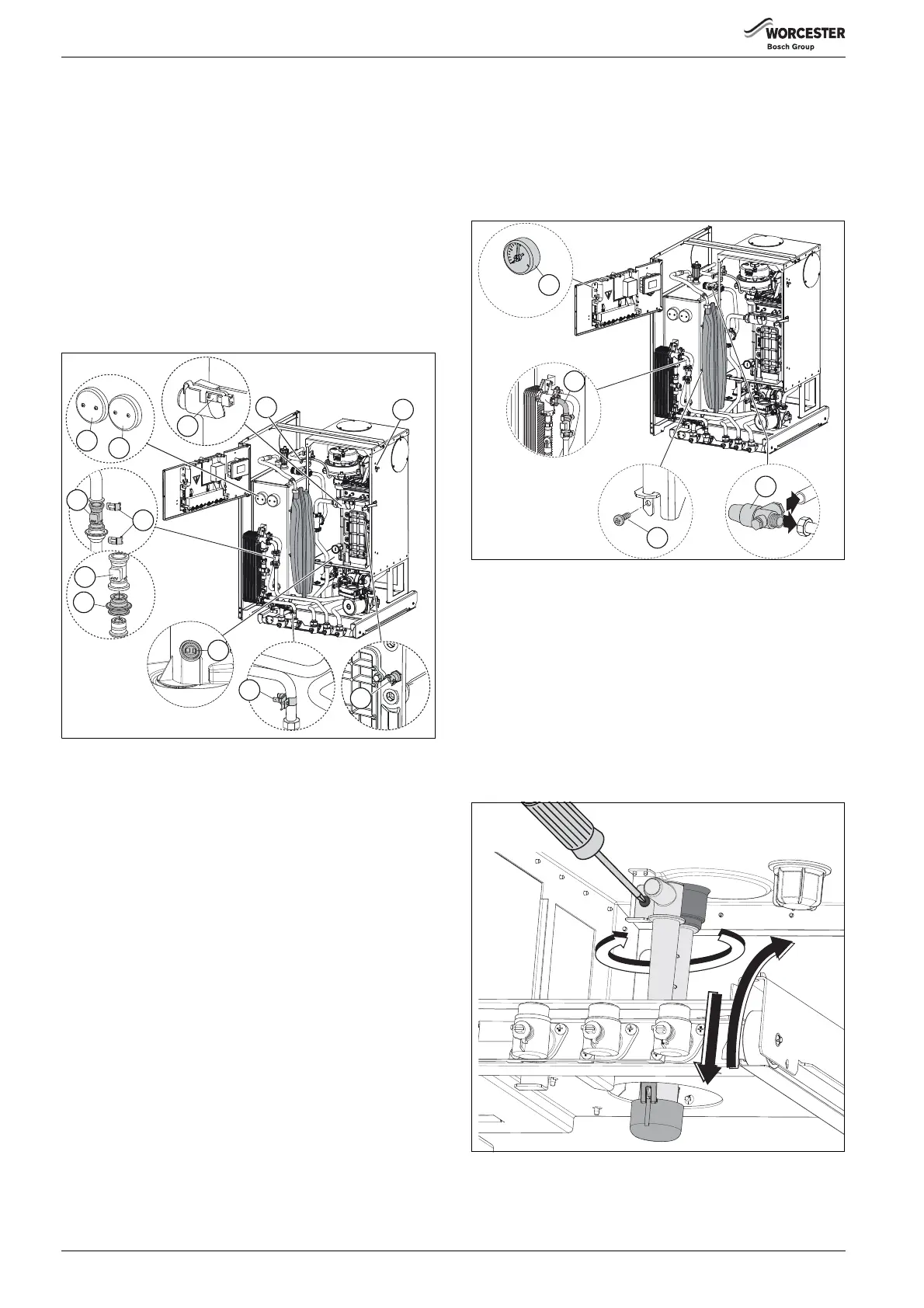
Fig. 64 Sensors
6.9.10 Domestic hot water heat exchanger
▶ Before removing the heat exchanger, close the mains water inlet
isolation valve and drain the hot water circuit. Close the CH isolating
valves and drain the appliance.
The pipe [2] may be removed between the flow sensor outlet and the
plate heat exchanger to improve access to the rear connections.
▶ Undo the two screws securing the plastic housing to the heat
exchanger.
▶ Remove the heat exchanger.
▶ To refit, follow the above in reverse. Ensure any seals that have been
disturbed are replaced.
6.9.11 Pressure gauge:
▶ Drain the appliance.
▶ Unplug the connection to the pressure relief valve.
▶ Release the pressure gauge from the clips on the rear of the control
panel.
6.9.12 Expansion vessel:
▶ Drain the appliance.
▶ Move the control panel into service position.
▶ Remove the locking screw [3] from vessel bracket.
▶ Undo the union connection at the top of the vessel.
▶ Swing the expansion vessel out and lift off the brackets.
▶ Set the pressure of the new vessel to that required by the system.
6.9.13 Pressure relief valve PRV:
▶ Drain the appliance.
▶ Disconnect the drain pipe from the valve [4]
▶ Undo the nut retaining the PRV to the flow pipe.
▶ Remove the clip from the PRV and disconnect the pressure gauge.
▶ Remove the valve.
▶ Replace the sealing washer and fit a new valve.
Fig. 65 Replacement parts
6.9.14 Condensate trap
▶ Remove the condensate pump, refer to section 6.9.4 on page 38
▶ Remove the screw retaining the trap
▶ Rotate the condensate trap by 90°
▶ Pull the trap down from the sump connection
▶ Angle the trap backwards and remove from the boiler
▶ Before replacing the trap, fill with at least 250ml of clean water
▶ Replacing the trap is the reverse of the removal procedure
▶ Reconnect the condensate pump and reconnect the pipe from the
trap
▶ Reconnect the condensate disposal pipe
Fig. 66 Condensate trap access
6720818077-17.1Wo
5
2
1
3
9
10
11
4
6
7
6
8

 Loading...


