SERVICING AND SPARES
Greenstar Highflow CDi
ErP
- 6720818077 (2016/04)36
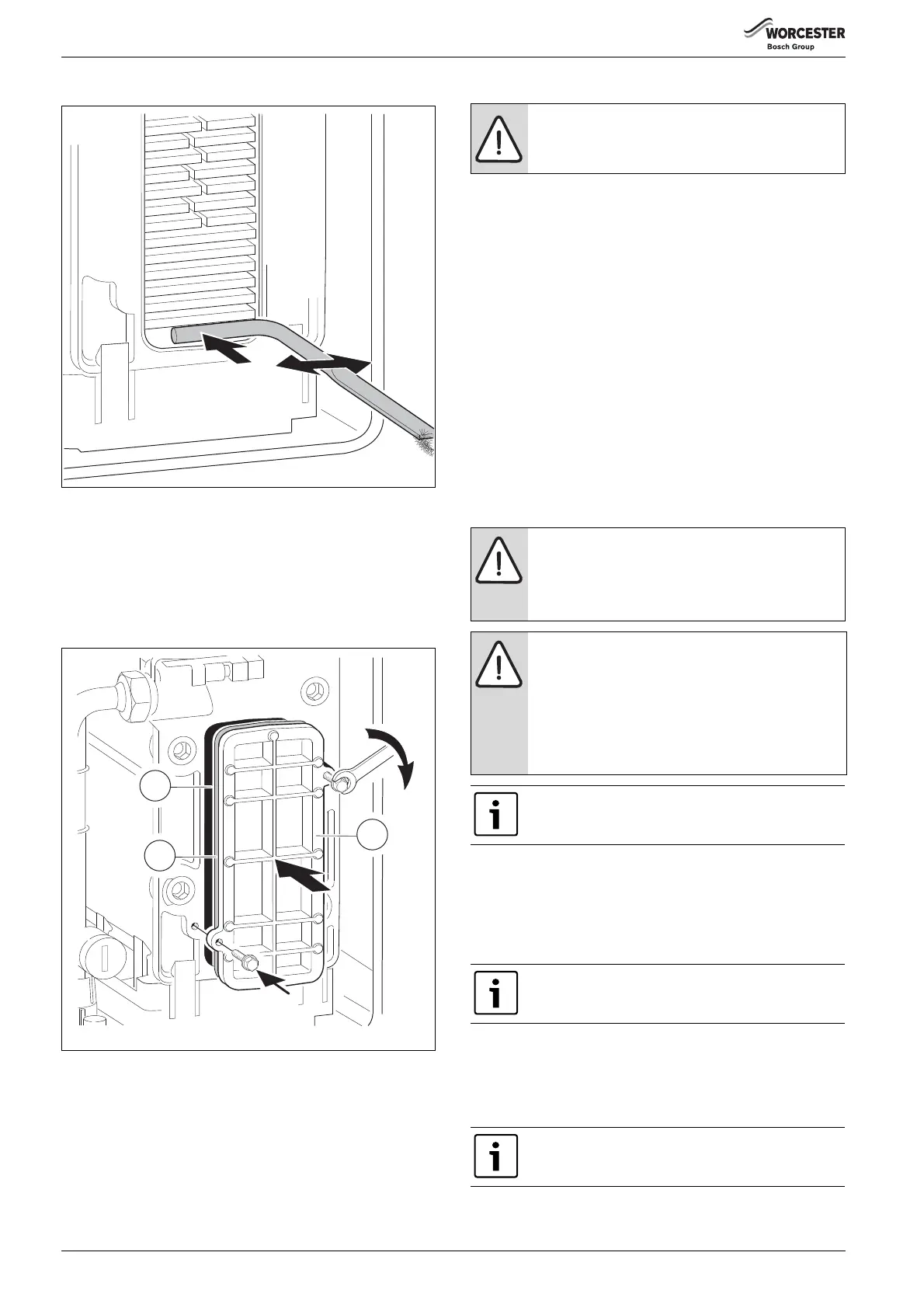
▶ Pour water into the top of the heat exchanger to flush out the debris.
Fig. 55
▶ Refit the cleaning access cover assembly in reverse order, the metal
plate [3] first, then the new seal [2], lastly the access cover [1].
▶ Refit the condensate trap.
▶ Pour 250ml of clean water into the heat exchanger to fill the
condensate trap.
▶ Hand tighten the bolts and then use a spanner to tighten the bolts a
further half turn.
Fig. 56
6.7.5 Re-assembly of the burner cover
▶ Refer to figure 48 and re-assemble the burner in reverse order
▶ Fit a new burner gasket seal [8].
▶ Refit the burner.
▶ Insert the burner cover under the rear nut [4a] and hand tighten.
▶ Assemble the washers/ spring [2b], and castellated nuts [2a], refer
to figure 48, on to the studs [2] to secure the burner cover to the heat
exchanger.
▶ Using a 10mm spanner, tighten the two castellated nuts [2a] until
the burner cover bottoms out on the heat exchanger.
▶ Using a 13mm spanner tighten the rear nut [4a]until the burner
cover bottoms out on the heat exchanger.
▶ The nuts will stop turning at this point, do not overtighten.
▶ If necessary, back the nuts off slightly until the hole for the clip [1] is
visible.
▶ Insert the clips [1] and secure.
▶ After re-assembly check that the CO/CO
2
levels are as described in
the section “Setting the air/gas ratio” on page 36.
6.8 Setting the air/gas ratio
To set the maximum CO
2
:
▶To adjust the CO
2
it will be necessary to first operate the boiler at
maximum output
▶ Press and hold down the Service engineer button [1] for 10 seconds
▶ Turn temperature control [2] to maximum, the boiler will then go to
maximum output
▶ Remove the combustion chamber cover
▶ Remove plastic cap and using a flat bladed screwdriver
▶ Set the maximum CO
2
(+ or -) using the adjuster [3]
▶ Replace the combustion chamber cover
▶ Check the maximum CO
2
referring to table 15
▶ Check the CO is less than 200ppm
6720818079-22.1Wo
2
1
3
NOTICE: Burner gasket seal
▶ Always replace the burner seal with a new one when
the joint has been disturbed.
NOTICE: SETTING THE AIR/GAS RATIO
▶ The air/gas ratio is factory set and should not
normally need adjustment
▶ Only adjust if the values are still out of range when all
other possible causes have been checked
NOTICE: COMBUSTION TESTING
▶ The setting of the air/gas ratio must be carried out by
a competent registered gas engineer, such as a Gas
Safe registered engineer or British Gas engineer.
Setting of the air/gas ratio must not be attempted
unless the person carrying out the test is equipped
with a combustion analyser conforming to BS 7927
and is competent in its use.
All CO/CO
2
readings must be taken with the combustion
chamber cover ON.
Adjustments can only be made with the cover off.
The control will resume normal operation after 15
minutes or if the Service engineer button [1] is pressed
for more than one second.
CO
2
should be measured 10 minutes after firing the
boiler

 Loading...


