SERVICING AND SPARES
Greenstar Highflow CDi
ErP
- 6720818077 (2016/04)38
6.9.2 PCB Control board
Access to boiler control components
▶ Remove the screws [1] to release the cover from the controller.
PCB Fuse
▶ Remove the fuse [2] and replace with a spare that is clipped on the
inside of the controller cover.
PCB
▶ Disconnect all electrical connections from the control board.
▶ Remove the screws [3] retaining the rear panel of the control and
remove the panel.
▶ After re-assembly check CO/CO
2
levels as described in the section
“Setting the air/gas ratio” on page 36.
Fig. 59 PCB
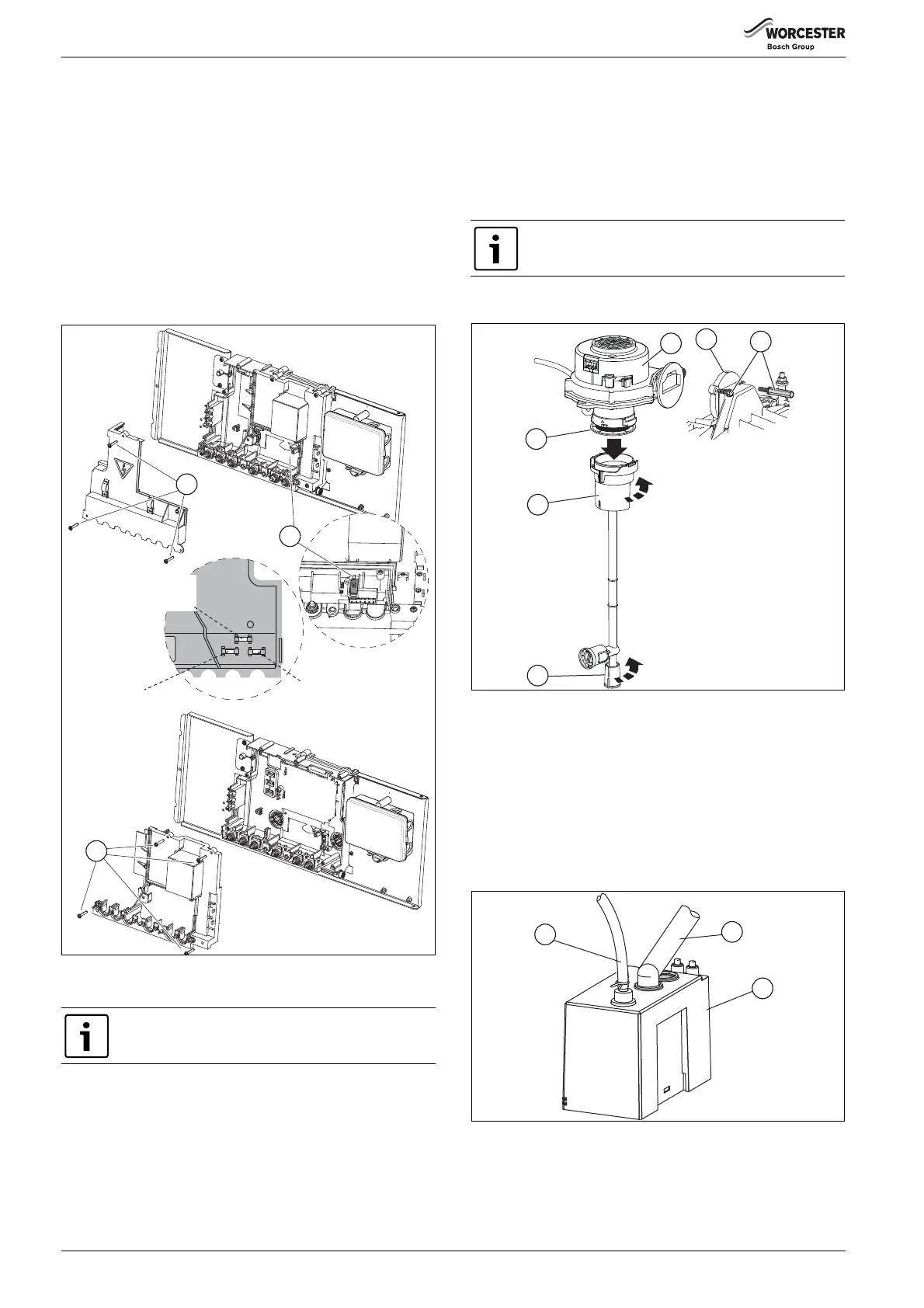
6.9.3 Fan assembly:
▶ Undo lower pipe union on gas pipe [5].
▶ Twist the mixer unit [4] with gas pipe [5] to separate from fan [1].
▶ Remove fan lead and earth connector.
The earth connector has a positive clip fixing.
▶ Remove fixing screws [3] attaching fan [1] to the burner cover [2].
▶ Remove fan [1].
▶ After re-assembly check that the CO/CO
2
levels are as described in
the section “Setting the air/gas ratio”.
Flap Valve:
▶ Undo lower pipe union on gas pipe [5].
▶ Remove pipe [5] by pushing upwards and towards the rear of the
boiler.
▶ Twist the mixer unit [4] with gas pipe [5] to separate from the fan
[1].
▶ Remove flap valve [6] from within fan intake [1] and replace.
▶ After re-assembly check that the CO/CO
2
levels are as described in
the section “Setting the air/gas ratio” on page 36.
Fig. 60 Fan assembly
6.9.4 Condensate pump
▶ Disconnect electrical connections in control box, see wiring
schematic in the ‘Fault finding and Diagrams’ section 7, page 43.
▶ Rotate the 15mm flexible tube [1] anti-clockwise and pull up to
remove from the pump.
▶ Remove black flexible pipe [2] from condensate pump. Take care as
there maybe condensate remaining in the pipe.
▶ Carefully remove the condensate pump [3] from the boiler and pour
any excess condensate into a suitable container for safe disposal.
Fig. 61 Condensate pump
Do not attempt to service the fan assembly and flap
valve if a CO/CO
2
analyser is not available.
6720818077-22.1Wo
T2.5A H250V F1
T500mA L250V F3
Spare Fuse order
T1.6A L250V F2
1
2
3
Ensure the flap valve is fitted correctly with rubber flap
upwards.
6720818079-10.1Wo
1
2
3
4
5
6

 Loading...


