COMMISSIONING
6720818077 (2016/04) - Greenstar Highflow CDi
ErP
29
▶ Measure the pressure with the boiler running at maximum.
– Refer to figure 33 for control panel guide
– Press Service engineer button [11] for more than ten seconds
and set Central Heating temperature to maximum.
– The Service engineer button [11] will illuminate continually and
the blue power indicator will pulse five times.
▶ Check the gas supply working pressure at the gas valve conforms to
values shown in figure 39 or figure 40.
Gas pressure within the system
Refer to the figures below for natural gas or L.P.G gas pressures.
The pressure at the boiler must not be less than the pressure read at the
meter minus:
• 1 mbar for Natural Gas
• 2.5 mbar for L.P.G.
The pressure drop from the meter to the gas valve must not be more
than:
• 2.5 mbar for Natural Gas
• 4 mbar for L.P.G.
If the pressure drops are greater than shown below, then this would
indicate a problem with the pipe work or connections within the system.
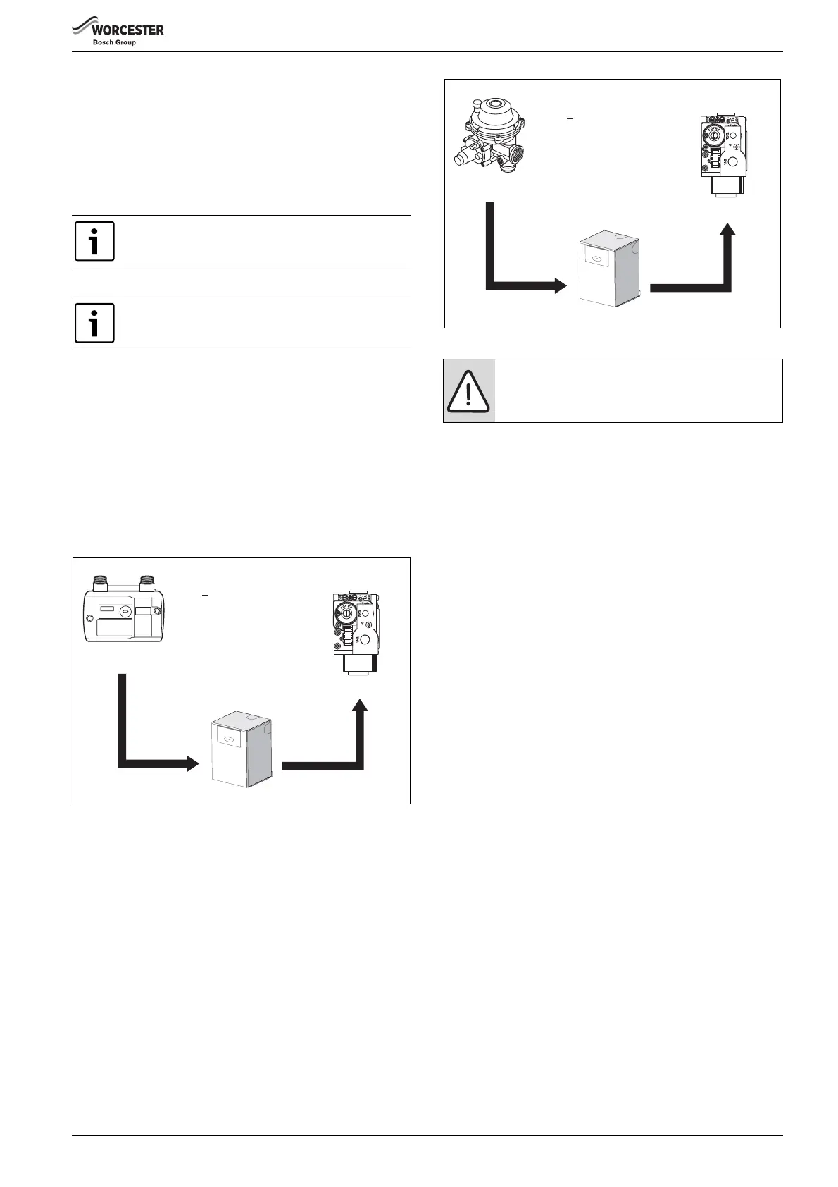
Fig. 39 Natural gas pressures
[≤ ] Equal to or less than
Fig. 40 L.P.G. pressures
▶ If pressure is satisfactory press the Service engineer button [11]
again and the boiler will return to normal operation.
▶ If left in the Service mode the control will return to normal operation
after 15 minutes.
▶ Re-seal the screw in the gas inlet pressure test point.
5.5.2 Checking the gas rate
▶ The gas rate should be measured at the gas meter after 10 minutes
operation at maximum, refer to technical data in section 2.2.
▶ Where a gas meter is not available (e.g. L.P.G.) the CO/CO
2
must be
checked to the units shown in the setting the air/gas ratio, refer to
section 6.8.
▶ If pressure and gas rate are satisfactory press the Service engineer
button [11] again and the boiler will return to normal operation.
– If left in the service mode the control will return to normal
operation after 15 minutes.
▶ Close the gas isolation valve.
▶ Remove the manometer.
▶ Re-seal the screw in the gas inlet pressure test point.
▶ Open the gas isolation valve.
▶ Ensure that there are no gas leaks.
▶ Replace the outer case.
Ensure inlet pressure is satisfactory with all other gas
appliances working.
The boiler must be running at maximum output rate
when performing the gas rate check.
Meter
Boiler inlet
Gas Control
valve
19 - 23 mbar
18 - 22 mbar
16.5 - 20.5 mbar
1 mbar
drop
1.5 mbar
drop
Natural Gas
< 2.5mbar
difference
6 720 815 062-44.1O
NOTICE:
Do not continue commissioning until the correct gas
pressure is achieved.
Gas Control
valve
L.P.G.
< 4.0mbar
difference
Regulator
Boiler inlet
32 - 45 mbar
29.5 - 42.5 mbar
28 - 41 mbar
2.5 mbar
drop
1.5 mbar
drop
6 720 815 062-45.1O

 Loading...


