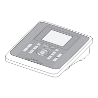
Connections – 7-pin sensor input jack on the underside
of the housing
– Screwless plug-in connections in the
housing using cable glands
Connection cross
section
0.5 ... 2.5 mm
2
Cable feeds 4 cable glands PG 13,5 / terminal range 10 ...
14 mm
Relay contacts Galvanically separated
Max. switching voltage 250 V AC or 30 V DC
Max. switching current 5 A (AC and DC)
Max. switching power 150 W (resistive load)
Relay K1 and K2 Programmable as:
– Signaling relay for failure of supply voltage
– Signaling relay for "frozen" outputs
– Limit monitor
–Timer
Switching behavior adjustable