Page 36 of 42 pages
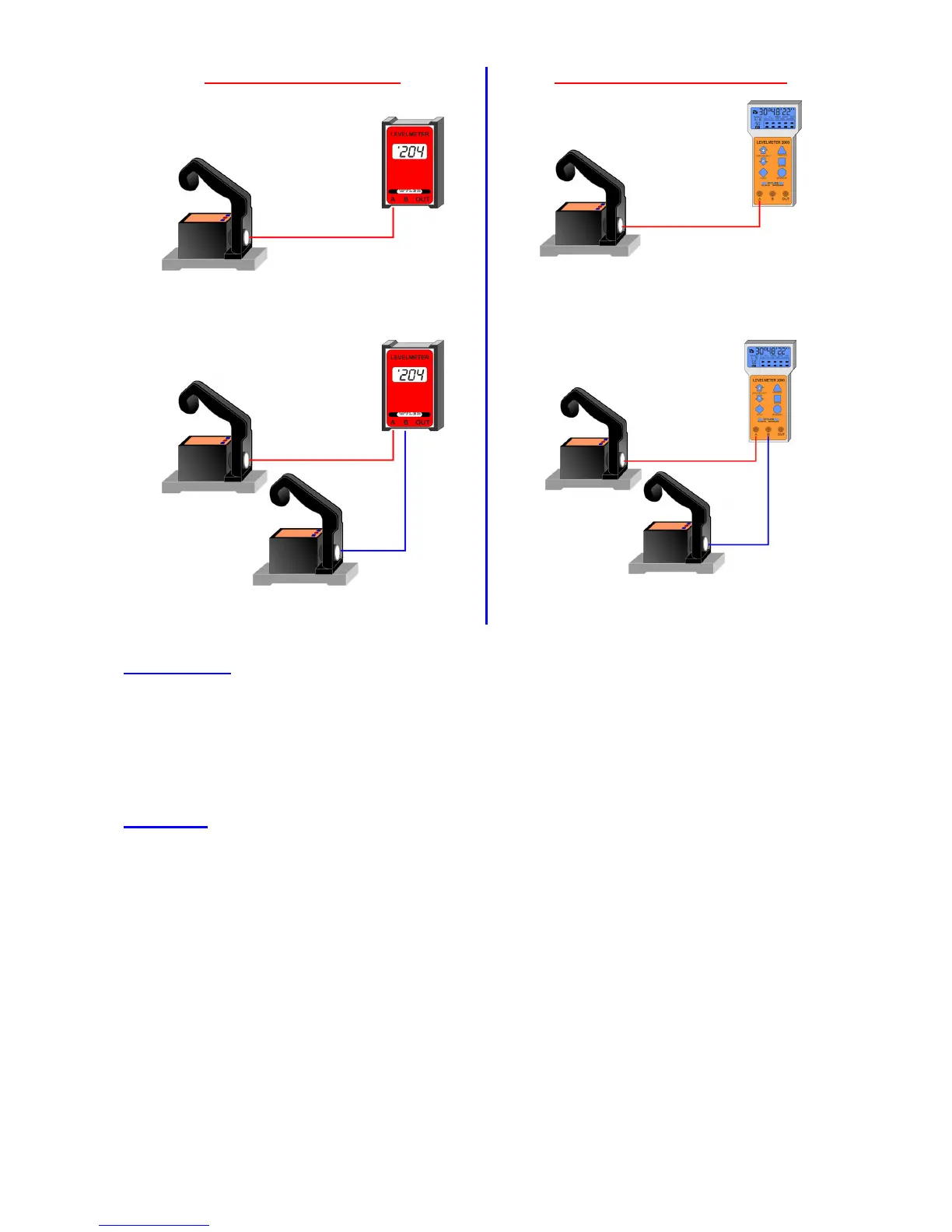
Possible configurations with LEVELTRONIC „NT“ 41
Analogue data transmission
Digital data transmission (RS485)
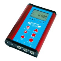
LEVELTRONIC „NT“ 41 with LEVELMETER C25
(red cover)
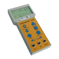
LEVELTRONIC „NT“ 41 with
LEVELMETER 2000
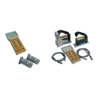
Two LEVELTRONIC „NT“ 41 with LEVELMETER C25
(red cover) for differential measurement
Two LEVELTRONIC „NT“ 41 with LEVELMETER 2000
for differential measurement
Function check
of the system LEVELTRONIC NT 11 combined with LEVELMETER C25/DC
a) LEVELMETER C25 power ON without cables connected
Low battery indication (XX:XX colon) must not appear
b) Connect LEVELTRONIC „NT“ with LEVELMETER C25, Socket "A"
c) LEVELTRONIC „NT“ cable to the right,
• Cable side of the instrument UP Display on LEVELMETER C25: ,1
• Cable side of the instrument DOWN Display on LEVELMETER C25: ‘1
Zero setting
of the system(absolute ZERO) LEVELTRONIC „NT“ 41 with LEVELMETER C25/DC
Prior to adjusting the zero point, the instrument should be allowed time to acquire the ambient, respectively the
work-piece temperature. Also the measuring system should have been switched on for about 1 min. (for
sensitivity of 1 µm/m about 3 minutes)
- Slide the LEVELTRONIC NT onto a flat, horizontally levelled surface (e.g. engineer's surface plate)
- The position of the LEVELTRONIC NT is to be marked on the surface.
- The display is to be set to zero by means of the potentiometer "ZERO" on the LEVELMETER C25
- Now the LEVELTRONIC NT is to be turned 180 degrees and slid exactly onto the previously
- By means of the potentiometer set the display on the LEVELMETER C25 to half the value now
showing.
- Now reverse the LEVELTRONIC NT once more. The display should now show the same value as
before but with reversed indication.
 Loading...