Pre-installation Planning
975-0012-01-02 Rev A 2–3
Mounting
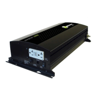
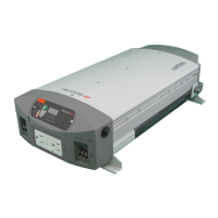
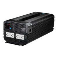
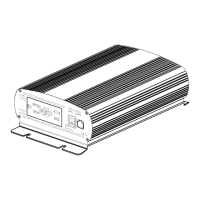
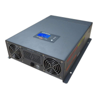
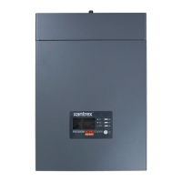
The National Building Code requires the inverter be mounted on a vertical surface
(or wall). The keyhole slots must not be used as the only method of mounting. The
purpose of the wall mounting requirement is to orient the inverter so that its
bottom cover, which has no holes, will not allow burning material to be ejected in
the event of an internal fire. Use 0.25-inch diameter bolts for mounting. The
mounting surface must be capable of supporting twice the weight of the inverter to
comply with UL 1741.
Ventilation
Install the inverter in a well ventilated area/enclosure for proper operation. The
inverter’s thermal shutdown point will be reached sooner than normal in a poorly
ventilated environment, resulting in reduced peak power output and surge
capability, as well as shorter inverter life.
The inverter contains an internal fan. Ensure the air vents and intakes are not
obstructed in any way. Provide a minimum clearance of 6 inches around the top
and sides of the inverter for ventilation.
Tools Required
The following tools may be required to complete this installation.
❐ #2 Phillips screw driver
❐ Slotted screw driver
❐ Assorted open-end wrenches
❐ Socket wrench and fittings
❐ Multimeter (True rms)
❐ Hole saw
❐ Level
❐ Wire strippers
❐ Torque wrench
❐ Electrical tape
❐ Pencil
❐ Utility knife
 Loading...
