Installation
2–12 975-0012-01-02 Rev A
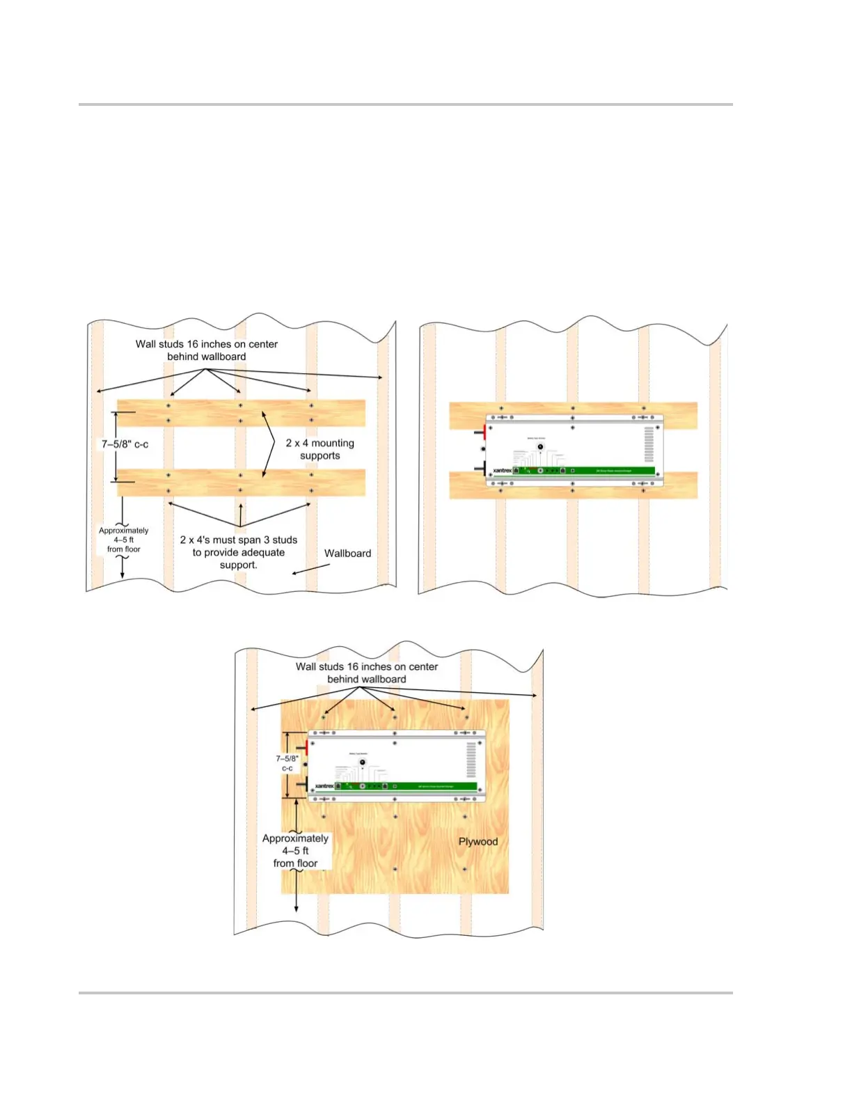
3. Secure the 2 x 4 with #10 wood screws (length to penetrate 1½ inches into the
studs) as shown in Figure 2-7.
4. Measure 7 5/8" from the center of the first 2 x 4 and draw another level line.
Place the center of the second 2 x 4 over this line and secure to the wall as
described in Step 5.
5. Using the dimensions illustrated in Figure 2-6, drill mounting holes into the
center of the 2 x 4’s for the inverter.
6. Secure the inverter to the 2 x 4’s using ¼ x 1½ inch lag bolts and washers.
Figure 2-7
Suggested Mounting Method
Figure 2-8
Mounting on Plywood
Ensure the plywood spans
across a minimum of three wall
studs for adequate support.
 Loading...