Do you have a question about the Xantrex XHR 100-10 and is the answer not in the manual?
| Brand | Xantrex |
|---|---|
| Model | XHR 100-10 |
| Category | Power Supply |
| Language | English |
Overview of the 1000 watt DC output power supplies, their applications, and key features.
Lists available voltage/current ranges, power factor correction, thermal shutdown, and front panel controls.
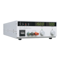
Details controls, LEDs, and meters on the power supply's front panel for operation and monitoring.
Describes rear panel connectors, SW1 programming switch, and J2 programming connector for remote functions.
Explains the function of the 8-position DIP switch for programming, monitoring, and shutdown selection.
Details the 12-terminal connector for remote programming, monitoring, and sense connections.
Provides wiring guidelines for the J2 connector, including safety warnings for high voltage models.
Presents detailed electrical performance parameters for different model ranges in tables.
Covers transient response, output hold-up time, and input conditions for the power supply.
Specifies operating and storage temperature, humidity, altitude, and pollution degree requirements.
Details physical characteristics including control types, connectors, cooling, mounting, size, and weight.
Illustrates the physical dimensions of the power supply unit with key measurements.
Outlines the essential steps for installing the power supply, from inspection to load connection.
Guides on performing initial checks, cleaning procedures, and proper packing for shipping or storage.
Details the process and requirements for returning units to Xantrex for service or repair.
Provides instructions on how to properly package the power supply for transit or long-term storage.
Covers rack mounting options and essential ventilation requirements for optimal operation and cooling.
Explains how to connect the power supply to the AC mains, including warnings and power cord information.
Describes procedures for verifying power-on, voltage mode, current mode, and front panel control operations.
Offers recommendations for load wiring, current capacity, wiring length, and noise reduction.
Illustrates recommended connections for single loads using both local and remote sensing.
Explains parallel and radial power distribution methods for connecting multiple loads.
Details how to set up the power supply for local or remote sensing of output voltage.
Explains the two basic operating modes (Constant Voltage, Constant Current) and control modes.
Describes how the supply automatically switches between voltage and current modes based on load.
Details the factory default settings for front panel operation and sense point configuration.
Step-by-step guide for setting the output voltage and current limit using front panel controls.
Covers configurations for series, parallel, and split supply operations to increase voltage or current.
Explains how to connect multiple supplies in series to achieve higher output voltages.
Details how to connect multiple supplies in parallel to achieve higher output currents.
Describes how to set up for two positive voltages or a positive-negative supply configuration.
Explains the OVP circuit's function and how to set the trip level from the front panel.
Provides methods to reset the Over Voltage Protection circuit after it has been activated.
Describes how to use the front panel STANDBY switch or J2 connector for output enable/disable.
Explains the OTP shutdown mechanism and selectable recovery options via SW1-8.
Offers operator-level checks for troubleshooting unusual or erratic operation before calling service.
Introduces controlling output voltage and current limit using external analog sources via the J2 connector.
Step-by-step guide for setting up switches and connections for analog remote programming.
Illustrates a specific configuration for programming output voltage and current limit remotely.
Explains how to monitor output voltage and current using readback signals via the J2 connector.
Describes the optional ISOL interface for isolated analog programming and readback.
Provides instructions for connecting and using the ISOL interface for programming and monitoring.
Outlines prerequisites, safety, and equipment needed for calibrating the power supply.
Details calibration procedures for front panel voltmeter, ammeter, and OVP functions.
Step-by-step guide to calibrate the front panel voltmeter accuracy.
Step-by-step guide to calibrate the front panel ammeter accuracy.
Instructions for calibrating the Over Voltage Protection trip level and preview function.
Explains how to adjust voltage and current programming circuits for accuracy.
Detailed steps for calibrating the voltage programming offset and scale.
Detailed steps for calibrating the current programming offset and scale.
Details how to adjust output voltage and current monitor circuits for accurate readback.
Steps to calibrate the output voltage monitor offset and range.
Steps to calibrate the output current monitor offset and range.