Installation
2–14 975-0298-01-01
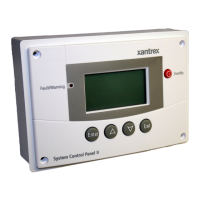
To surface mount the System Control Panel:
1. Using the supplied template sticker as a guide, mark the locations for
two mounting screws and the access hole for the Xanbus cables.
2. Using a hole saw, cut out the access hole for the Xanbus cable(s).
3. Route the Xanbus cable(s) from other Xanbus-enabled devices inside
the wall and through the access hole.
4. Attach the mounting bracket with two #6 screws.
5. Connect the Xanbus cable(s) (and terminator if necessary) to either
network input on the back of the System Control Panel.
Connect a network terminator to the System Control Panel if it is the
last device at the end of a daisy chain network layout.
6. Place the unit into the mounting bracket and secure it with four #6
screws. See Figure 2-11.
7. Peel off the protective plastic coating covering the screen and
indicator light.
Important:
To ensure communication signal quality, the network must be
terminated at each end with a terminator.
Figure 2-11
Surface Mounting the System Control Panel
 Loading...