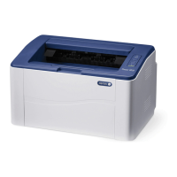
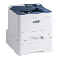
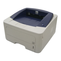
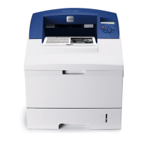
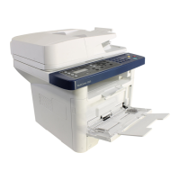
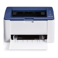
Xerox® Phaser® 3020 Printer
BLOCK SCHEMATIC DIAGRAMS
June, 2014
TABLE OF CONTENTS
This document contains wiring and mechanical power data for the Xerox® Phaser® 3020 Printer.
These block schematic diagrams are supplemental to the diagnostic and troubleshooting information
found in the Xerox Phaser 3020 Service Manual.
Every effort has been made to achieve accuracy on these schematics. However, if a difference is
noted between these schematics and the Xerox service documentation the service documentation
takes precedence.
CHAIN 1 POWER
1.1 AC / LOW VOLTAGE and HIGH VOLTAGE POWER /
INTERLOCKS
CHAIN 3 COMMUNICATIONS
3.1 PRINTER COMMUNICATIONS
CHAIN 4 MAIN DRIVE
4.1 MAIN DRIVE
CHAIN 6 LSU
6.1 LSU
CHAIN 7 PAPER FEED AND REGISTRATION
7.1 PAPER FEED AND REGISTRATION
CHAIN 9 XEROGRAPHICS
9.1 PRINT MODULE
CHAIN 10 FUSING
10.1 FUSING
Prepared by:
Content Development and Language Services - North America
Xerox Corporation
800 Phillips Road; Building 0218-01A
Webster, New York 14580 USA
©2014 Xerox Corporation. All rights reserved. Xerox® and the sphere of connectivity design are
trademarks of Xerox Corporation in the US and/or other countries..
 Loading...
