June 2014
4-7
Xerox® Phaser® 3020 Printer Service Manual
REP 1.5, REP 1.6
Repairs
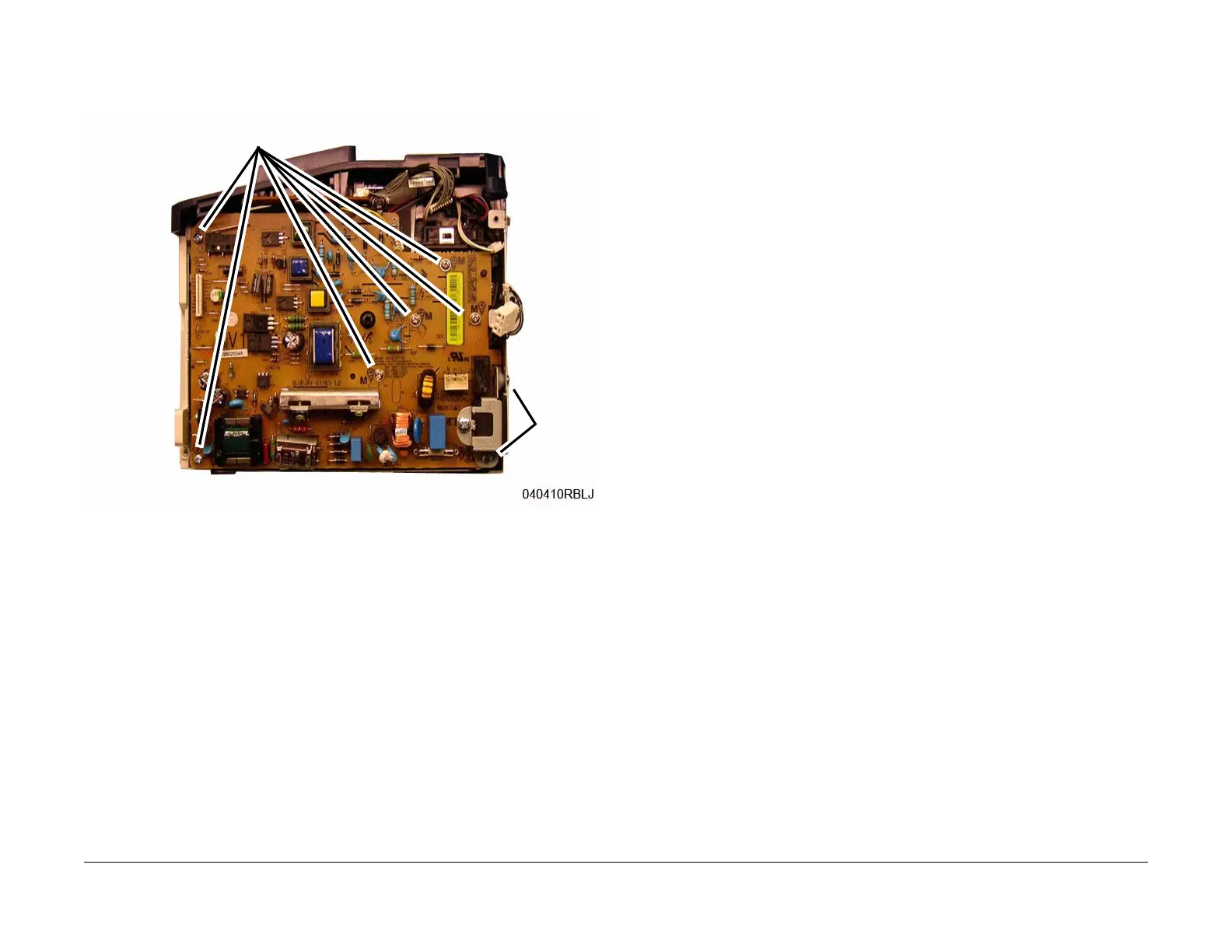
NOTE: Be careful not to lose the High Voltage Spring Contacts when removing the LVPS
/ HVPS PWB from the Frame.
6. Remove the screws (8) and the LVPS / HVPS PWB (Figure 2).
Figure 2 LVPS / HVPS PWB Screws
Replacement
NOTE: Tapered Plastic Screws and Round Machine Screws are used to hold the PWB to the
frame. Make sure that the Plastic Screws go into plastic components and Machine Screws go
into the metal frame.
Install the components in the reverse of removal.
REP 1.6 Main PWB
Parts List on PL 1.1
Removal
WARNING
Do not perform repair activities with the power on or electrical power supplied to the
machine. Some machine components contain dangerous electrical voltages that can
result in electrical shock and possible serious injury.
DANGER: Ne pas effectuer de dépannnage avec le contact principal activé ou avec l'ali-
mentation électrique appliquée à la machine. Certains éléments de la machine compor-
tent des tensions électriques dangereuses qui peuvent causer un choc électrique et de
graves blessures.
AVVERTENZA: Non effettuare alcuna riparazione con l'alimentazione elettrica inserita.
Alcuni componenti contengono corrente ad alta tensione che può provocare forti
scosse e gravi ferite.
VORSICHT: Es dürfen erst Reparaturarbeiten durchgeführt werden, wenn das Gerät aus-
geschaltet ist oder der Netzstecker nicht mehr mit der Stromquelle verbunden ist. Ein-
ige Komponenten des Gerätes sind stromführend und können daher zu ernsthaften
Verletzungen oder Stromschlägen führen.
AVISO: No realice reparaciones con la máquina encendida o conectada a la corriente.
Algunos componentes de la máquina contienen voltajes eléctricos peligrosos que
pueden producir una descarga eléctrica y causar daños graves.
1. Record the machine serial number from the Data Plate (located on the rear cover beneath
the bar code) or from a Configuration Report printed prior to installing the new PWB. To
print a Configuration Report, select from the PWS; [Easy Print Manager, Machine Set-
ting, Print Information, Configuration].
2. Switch Off the Printer and unplug the Power Cord.
3. Remove the Right Cover (REP 1.2).
Screws
Screws