June 2014
4-22
Xerox® Phaser® 3020 Printer Service Manual
REP 1.14, REP 1.15
Repairs
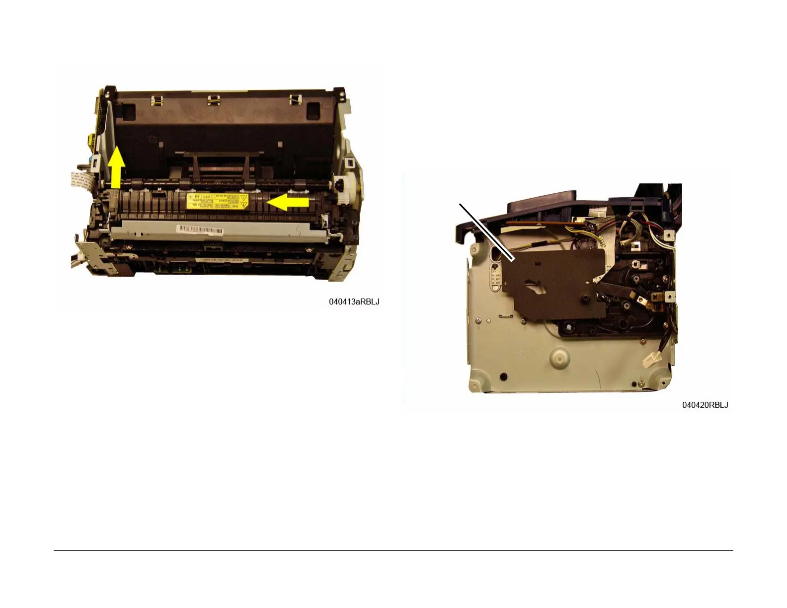
6. Remove the Fuser Module (Figure 3):
Lift the left side (viewed from the rear) of the user, then slide it to the left and remove it.
Figure 3 Fuser Removal (Top View)
Replacement
NOTE: Tapered Plastic Screws and Round Machine Screws are used to hold the PWB to the
frame. Make sure that the Plastic Screws go into plastic components and Machine Screws go
into the metal frame.
NOTE: The top right Tapered Plastic Screw (viewed from the rear) is different than the other
plastic screws in the printer, make sure it is installed in the correct location during replacement,
refer to (Figure 2).
Install the components in the reverse of removal.
REP 1.15 LSU Cables
Parts List on PL 3.6
Removal
1. Switch Off the Printer and unplug the Power Cord.
2. Remove the following covers:
a. Left and Right Side Covers (REP 1.2).
b. Rear Cover (REP 1.3).
c. Front Cover (REP 1.1).
3. Remove the Main PWB (REP 1.6), and the LVPS / HVPS PWB (REP 1.5).
4. Remove the Insulator Strip (Black) from behind the LVPS / HVPS PWB (Figure 1).
Figure 1 Insulator Strip
Insulator Strip