June 2014
4-12
Xerox® Phaser® 3020 Printer Service Manual
REP 1.9
Repairs
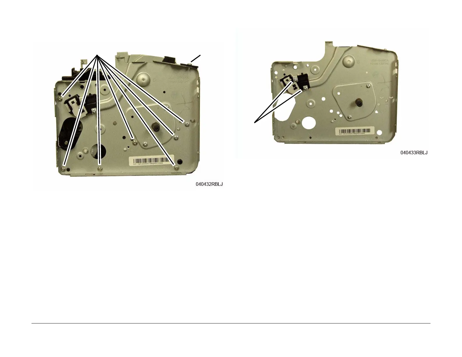
7. Remove the Left Frame and Drive Motor (Figure 3):
a. Remove the LSU Cover screw (1).
b. Remove the screws (7) and the Left Frame.
Figure 3 Left Frame Removal
8. Remove the Guide from the Left Frame (2 screws) (Figure 4).
Figure 4 Guide Removal
Replacement
NOTE: Tapered Plastic Screws and Round Machine Screws are used to hold the PWB to the
frame. Make sure that the Plastic Screws go into plastic components and Machine Screws go
into the metal frame.
Install the components in the reverse of removal.
NOTE: The Frame is flexible and can be bowed out if the screws are not tightened in the cor-
rect order.
Reinstall the Frame as follows so it seats flush against the printer internal modules.
1. Align the Left Frame on to the internal modules.
2. Install, but do not tighten, the screws (7) (Figure 3).
3. Tighten the Frame screws from the center of the Frame:
To the Front of the printer, then to the Rear of the Printer.
b - Screws
a - Screw
Screws