x
Service Manual
Circuit Description
12-6
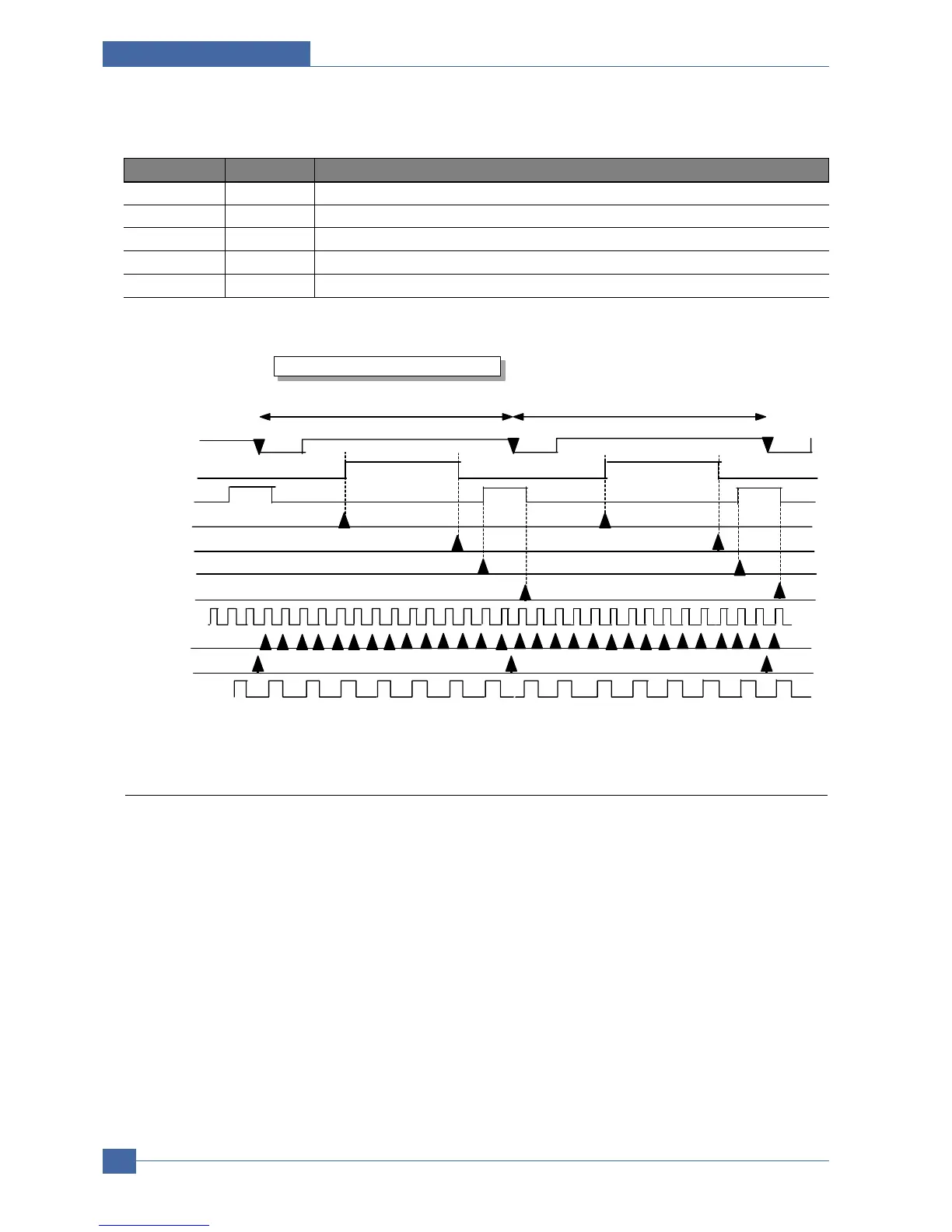
The main signals used in LSU Controller are shown in the table.
12.1.5 ADC Controller
Jupiter4E ADC Controller has 3 analog input channels.
It automatically converts the 3 channels in turns with 10 bit 500KSPS adc1275x_pc, and also it makes the conversion
on the desired time by manually controlling STC of the register. After finishing the conversion, it makes the interrup-
tion to be pending. When AD conversion of 3 rd channel ends for the PI Control of LSU, it sends the 10bit digital data
converted with the latch short pulse signal to LSUC.
Name Direction Description
PVC-VDO I The video data output from PVC.
nLREADY I Its activity becomes low as the polygon motor of LSU gets the regular speed.
nHSYNC I It informs the beginning of one line. It is the same as nLSYNC of PVC.
nPSync 0 It is inputted to nFSync of PVC.
LSU_VDO 0 The completed video data output by masking video window on PVC_VOD.

 Loading...