24 www.xilinx.com KC705 Getting Started Guide
UG883 (v4.0.1) May 28, 2014
Advanced Bring-up Using the Base Targeted Reference Design
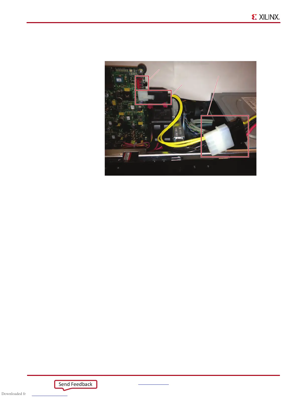
2. Figure 13 shows the 12V power connection. Connect the 12V ATX power supply’s
available 4-pin connector to the board (J49) via a 4-pin to 6-pin PCIe adapter cable.
Toggle the Power switch SW15 to the ON position.
3. Make sure the connections are tight, and then power on the PC system.
Note:
If the user wishes to boot Linux from the Fedora 16 Live DVD, place the DVD in the PC’s
DVD-ROM drive as soon as the PC system is powered on.
X-Ref Target - Figure 13
Figure 13: Power Supply Connection
UG883_13_121112
SW15
J49 6-pin
Connector
12V ATX Power
Supply Plugged
into the 4-pin
Connector

 Loading...


