ZCU104 Board User Guide 36
UG1267 (v1.1) October 9, 2018 www.xilinx.com
Chapter 3: Board Component Descriptions
The USB3320 ULPI U116 transceiver circuit (see Figure 3-4) has a Micrel MIC2544 high-side
programmable current limit switch (U121). This switch has an open-drain output fault flag
on pin 2, which turns on LED DS51 if over current or thermal shutdown conditions are
detected. DS51 is located in the U116 circuit area near pushbutton SW4 (Figure 2-1, callout
20).
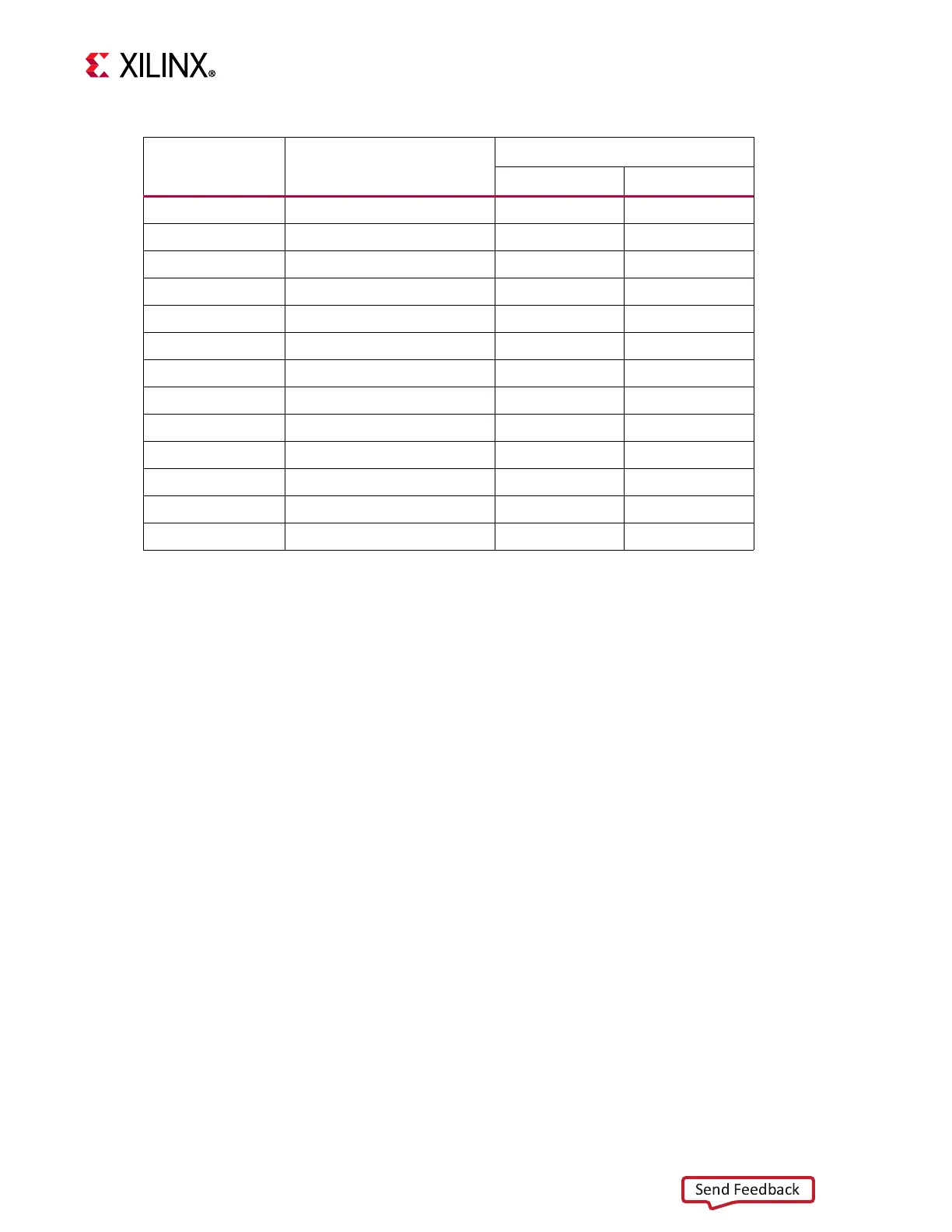
Table 3-7: USB 2.0 ULPI Transceiver Connections to XCZU7EV MPSoC
XCZU7EV (U1) Pin Net Name
USB3320 U116
Pin # Pin Name
U168.4 ULPI0_RST_B
(1)
27 RESET_B
H31 MIO58_USB_STP
(2)
29 STP
G30 MIO53_USB_DIR 31 DIR
G29 MIO52_USB_CLK 1 CLKOUT
G33 MIO55_USB_NXT 2 NXT
G34 MIO56_USB_DATA0
(2)
3 DATA0
H29 MIO57_USB_DATA1
(2)
4 DATA1
G31 MIO54_USB_DATA2
(2)
5 DATA2
H32 MIO59_USB_DATA3
(2)
6 DATA3
H33 MIO60_USB_DATA4
(2)
7 DATA4
H34 MIO61_USB_DATA5
(2)
9 DATA5
J29 MIO62_USB_DATA6
(2)
10 DATA6
J30 MIO63_USB_DATA7
(2)
13 DATA7
Notes:
1. PS_POR_B (U1.M24) or PS_MODE1 (DIP SW6.2) drive U116 RST_B via OR gate U168.
2. These nets are 30Ω series resistor coupled.