EasyManuals Logo

Xilinx ZCU104 User Manual

Xilinx ZCU104
92 pages
To Next Page IconTo Next Page
To Previous Page IconTo Previous Page
Page #49 background imageLoading...
Page #49 background image
ZCU104 Board User Guide 49
UG1267 (v1.1) October 9, 2018 www.xilinx.com
Chapter 3: Board Component Descriptions
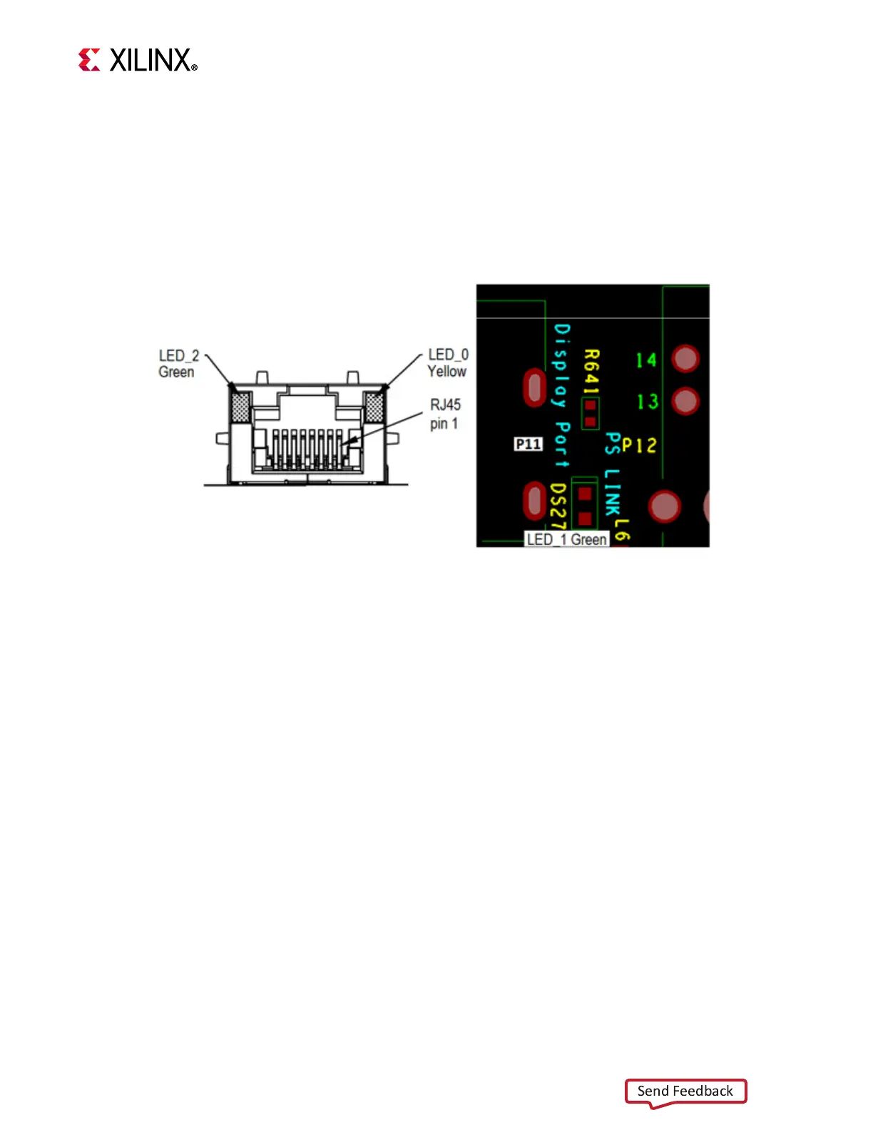
The DP83867IRPAP PHY LED indicators are shown in Figure 3-11.
LED_0 is the RJ-45 P12 bezel right-side yellow LED, link established indicator.
LED_2 is the RJ-45 P12 bezel left-side green LED, TX/RX activity indicator.
LED_1 is the green DS27 LED, mounted on the ZCU104 board top between the display
port connector P11 and the Ethernet RJ-45 connector P12, indicates the 1000BASE-T
link is established.
X-Ref Target - Figure 3-11
Figure 3-11: Ethernet PHY Status LEDs
X20116-012618
Send Feedback

Table of Contents

Other manuals for Xilinx ZCU104

Questions and Answers:

Question and Answer IconNeed help?

Do you have a question about the Xilinx ZCU104 and is the answer not in the manual?

Xilinx ZCU104 Specifications

General IconGeneral
BrandXilinx
ModelZCU104
CategoryMotherboard
LanguageEnglish

Related product manuals