bit4 (voltage enabled): at 1, indicates that the power supply voltage is applied to the PDS.
bit5 (quick stop): at 0, indicates PDS receives quick stop requirements. The bit logic of quick stop is effective
under 0. Please note that other bit logic and opposite actions are performed.
bit11(internal limit active): it is subject to internal restrictions.
bit13,12(operation mode specific): the following indicates the change of inherent OMS bit in control mode. (For
details, please refer to the chapter of related objects of each control mode.)
4.6.2.4 Control mode setting
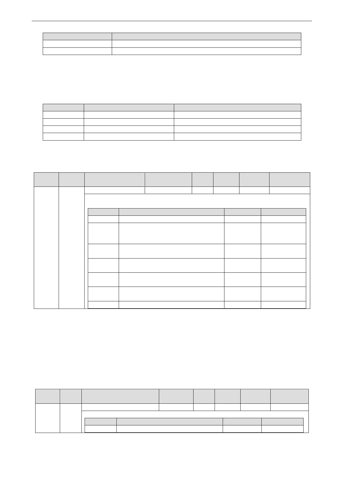
1. Modes of operation (6060h)
The control mode is set through 6060h(Modes of operation).
Set the control mode of servo driver.
Non corresponding control mode setting is prohibited.
No mode changed/No mode assigned
(No control mode change/no control
mode assignment)
Profile position mode
(Profile position control mode)
Profile velocity mode
(Profile speed control mode)
Torque profile mode
(Profile torque control mode)
Homing mode
(origin reset position mode)
As 6060h (Modes of operation) is default = (No mode change/no mode assigned), please set the control mode
value after the power is put into use. When the setting value of 6060h and 6061h is 0, if the PDS status is migrated
to Operation enabled, E-881 will occur (control mode setting fault protection).
After the initial state 6060h=0 (No mode assigned) converted to supportable control mode (PP, PV, TQ, HM), set
6060h=0 again, this case is seemed as “No mode changed”. Switching of control mode cannot be performed.
(keep previous control mode).
2. Modes of operation display (6061h)
The confirmation of servo driver internal control mode is performed as 6061h (Modes of operation display). After
6060h (Modes of operation) is set, please confirm whether the action of this object is feasible through detecting.
Indicates the present control mode.
 Loading...

