Page 36 5 Series
5 Series 5 Series
5 Series Operator’s Manual
AES Inputs and Outputs
The 5 Series units have a full AES implementation built in as standard. This allows the unit to both receive digital audio
directly, and to transmit digital audio on to other devices. The switching of input and output can be performed
independently, and the inclusion of sample rate converters on the inputs allows the unit to accept sample rates from
32kHz up to 192kHz.
AES Input
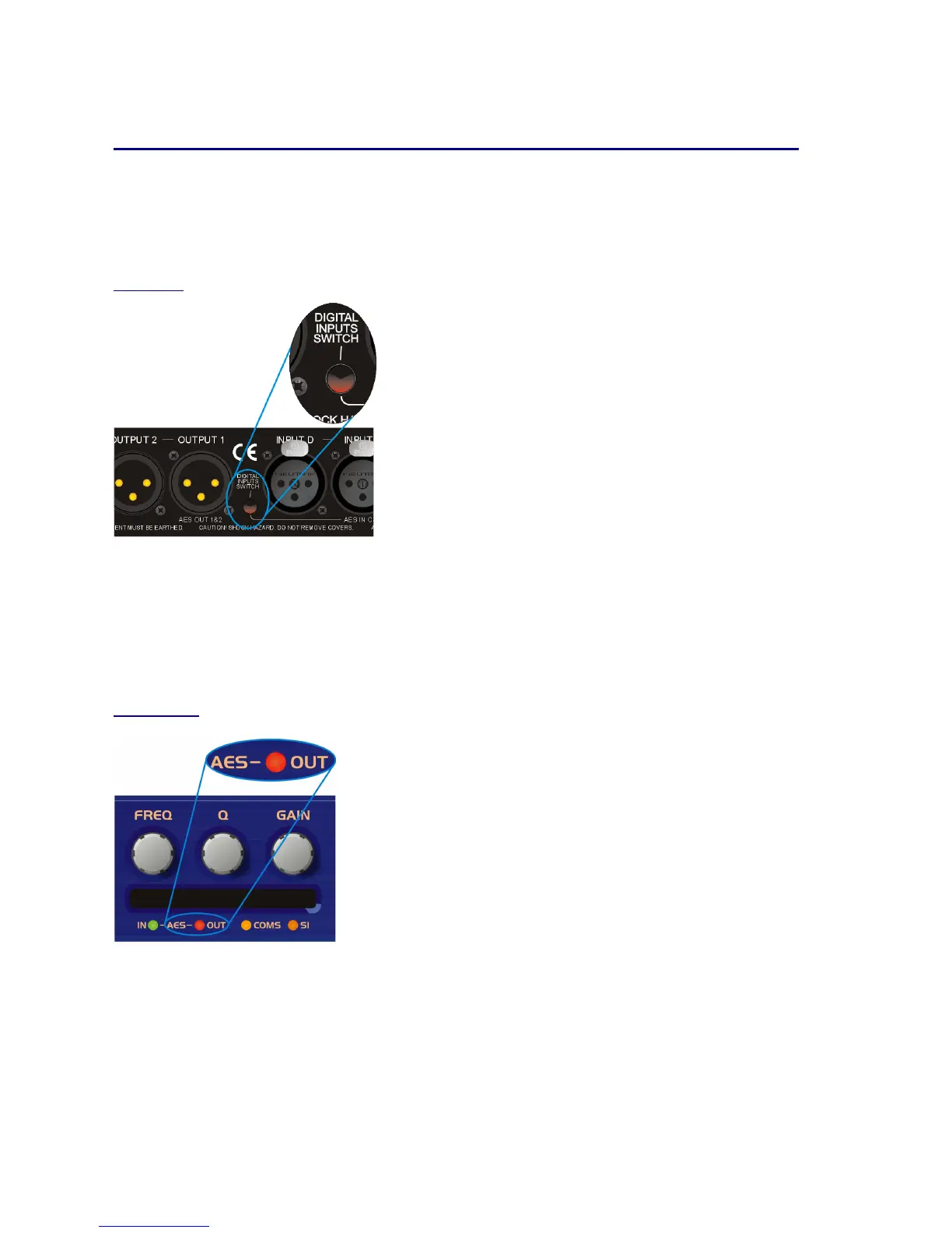
Input selection is via a recessed switch on the rear panel of the unit,
between input D and output 1. A red LED inside this aperture illuminates
to show that the AES digital inputs have been selected.
Please power the unit down before switching into AES input mode
to avoid any sudden changes in output level.
Whilst you can switch to AES mode with the power on, we advise only
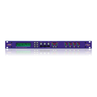
A complimentary LED on the front panel below the PCMCIA card also
illuminates. The switch controls the rear panel LED directly, whilst the
front panel one is via the processor, allowing it to relay a little more
information.
If it is flashing, this means that AES inputs have been selected but have not
locked. Once a stable AES signal is being received, it will be permanently illuminated.
The AES inputs are marked on the rear panel –
for channels A & B use input A,
and for channels C & D use input C.
AES Output
AES outputs are selected through the AES menu:
AE
AEAE
AES/EBU Sub Menu
S/EBU Sub MenuS/EBU Sub Menu
S/EBU Sub Menu
Output Selection
Output SelectionOutput Selection
Output Selection
Pressing
ENTER
ENTERENTER
ENTER
and then using
BACK
BACKBACK
BACK and NEXT
NEXTNEXT
NEXT chooses either
Analogue
AnalogueAnalogue
Analogue or Digital
DigitalDigital
Digital. Press
ENTER
ENTERENTER
ENTER
again to confirm selection.
The AES outputs are marked on the rear panel –
Channels 1 & 2 use Output 1
Channels 3 & 4 use Output 3
Channels 5 & 6 use Output 5 (DP548 only)
Channels 7 & 8 use Output 7 (DP548 only).